
Embedded type end cover sealing structure

An end cap sealing and sealing structure technology, applied in transmission parts, belts/chains/gears, mechanical equipment, etc., can solve the problems of easy oil leakage and small space, achieve simple and beautiful design, and solve the problem of oil leakage in small space Effect

Inactive Publication Date: 2013-09-11
JIANGSU HEFUTE GEAR MFG
View PDF4 Cites 1 Cited by
  • Summary
  • Abstract
  • Description
  • Claims
  • Application Information

AI Technical Summary

Problems solved by technology

However, when the center distance is relatively small and the space is relatively small, if the end cover with this structure is used, one is that there is no place to drill bolt holes, and it is not easy to use bolts to fix it, and the other is that the space is small and oil leakage is easy. a big problem

Method used


Image

  • Embedded type end cover sealing structure

Examples


Embodiment

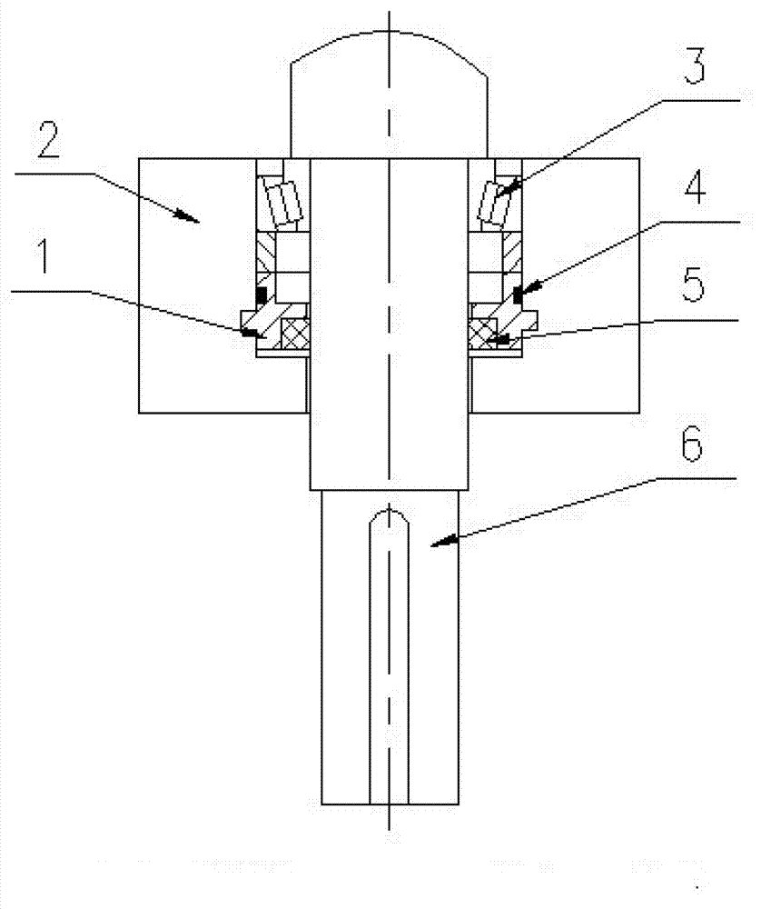
[0018] Such as figure 1 As shown, an embedded end cover sealing structure includes a power output shaft 6, a bearing seat 2 is provided at one end of the power output shaft 6, and a bearing 3 in contact with the power output shaft is provided in the bearing seat 2. A sealing structure is provided between the bearing seat 2 and the power output shaft 6 .

[0019] In this embodiment, an embedded end cover 1 matching the power output shaft 6 is arranged inside the bearing seat, and a sealing structure is arranged between the embedded end cover 1 and the power output shaft 6 .

[0020] The sealing structure includes a sealing ring arranged on the embedded end cover 1 , and the sealing ring is an O-ring 4 . In this embodiment, the O-ring 4 is an annular O-ring made of rubber material.

[0021] In this embodiment, the sealing structure includes a sealing element arranged between the embedded end cover and the power output shaft. The sealing member is a statically sealed oil seal ...


PUM


Abstract

The invention discloses an embedded type end cover sealing structure which comprises a power output shaft and is characterized in that a bearing seat is arranged at one end of the power output shaft, and a bearing in contact with the power output shaft is arranged in the bearing seat. A sealing structure is arranged between the bearing seat and the power output shaft. An embedded end cover matched with the power output shaft is arranged in the bearing seat, and the sealing structure is arranged between the embedded end cover and the power output shaft. By means of the embedded type end cover sealing structure, an oil leakage condition is avoided effectively, and axial locating is achieved through the box body bearing seat, an embedded end cover stop opening and a power output shaft shoulder. In addition, the embedded type end cover sealing structure is simple and attractive in design, has a dual-sealing effect and effectively solves the problems of small space and oil leakage.

Description

technical field [0001] The invention relates to an embedded end cover sealing structure. Background technique [0002] The planetary reducer is a widely used industrial product. Its performance is comparable to other military-grade reducer products, but it has the price of industrial-grade products. It is mainly used for the slewing mechanism of tower cranes, and can also be used as a supporting component Lifting, excavation, transportation, construction and other industries. [0003] At present, the end caps used on the reducer are all positioned by the seams, and the bolts are closed. A certain space is required between the end caps to place and screw the bolts. However, when the center distance is relatively small and the space is relatively small, if the end cover with this structure is used, one is that there is no place to drill bolt holes, and it is not easy to use bolts to fix it, and the other is that the space is small and oil leakage is easy. A major drawback. ...

Claims


Application Information

Patent Timeline
Patent Type & Authority Applications(China)
IPC IPC(8): F16H57/029
Inventor 陶菊芬宋廷
Owner JIANGSU HEFUTE GEAR MFG
Learn More