


Quick Research
Generate reliable direction feasibility study reports for your R&D in just a few steps.

Technical Q&A
Discover and master advanced knowledge NOW. Basics, ideas, possibilities, all at once.

Find Solutions
As an expert in R&D theories, this can generate solutions to your technical problems instantly.

Evaluate Feasibility
Analyze your overall solution with one click, know your potential R&D risks in advance.

Monitor Landscape
Get weekly tech updates, stay abreast of the latest tech innovations and key insights.
Engine continuously variable intake tumble control mechanism and engine
A control mechanism and engine technology, applied in engine control, combustion engine, machine/engine, etc., can solve the problem of variable tumble flow not working, and achieve the effect of improving airflow movement and better tumble flow effect.
- Summary
- Abstract
- Description
- Claims
- Application Information
AI Technical Summary
Problems solved by technology
Method used
Image

Examples
Embodiment 1
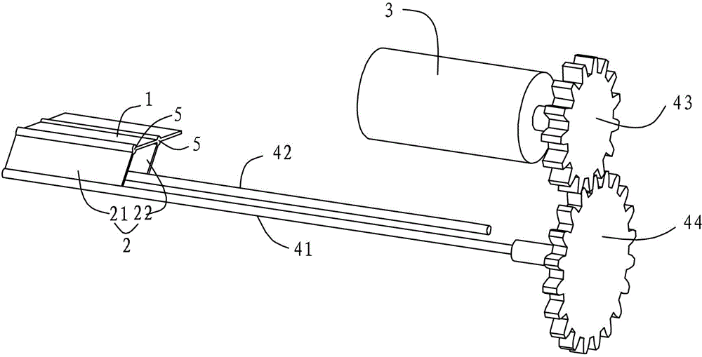
[0023] This embodiment relates to an engine continuously variable intake tumble flow control mechanism, which is arranged in the intake duct of the engine, figure 1 As shown, it includes a top plate 1 arranged horizontally in the state shown in the figure, a supporting and blocking device 2 connected to the bottom of the top plate 1, and a power transmission mechanism connected between the supporting and blocking device 2 and the power output device 3. The power is transmitted to the supporting and blocking device 2 through the power transmission mechanism, so that the supporting and blocking device 2 always maintains the horizontal state of the top plate 1 while driving the top plate 1 to have a vertical displacement. In this embodiment, the power output device 3 uses a servo motor.
[0024] Wherein, the supporting and blocking device 2 includes a first side plate 21 and a second side plate 22 of the same size which are arranged in parallel and connected under the top plate 1. Th...
Embodiment 2
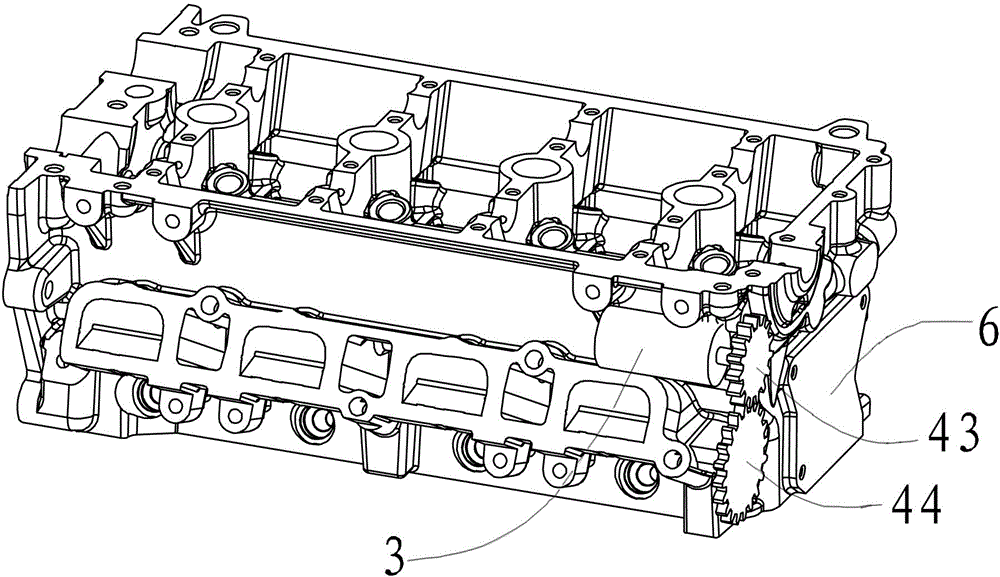
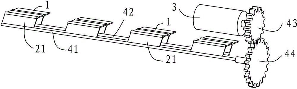
[0029] This embodiment relates to an engine, and is an application of the continuously variable intake tumble flow control mechanism of the engine involved in the first embodiment. by figure 2 Combine image 3 As shown, the engine of this embodiment has four intake ducts, and each intake duct is provided with the engine continuously variable intake tumble flow control mechanism involved in the first embodiment. by image 3 As shown, the engine continuously variable intake tumble flow control mechanism is basically the same as the first embodiment, except that four sets of supporting and blocking devices 2 and the top plate 1 are used in conjunction with each other, and they share one rotating shaft 41, one Root driven shaft 42, a power output device 3 and a speed reduction structure.
[0030] by figure 2 As shown, the power output device 3 is fixedly arranged on the main body 6 of the engine, and the rotating shaft 41 connected with the driven gear 44 extends from the outside o...
PUM
 Abstract
Description
Claims
Application Information
 - R&D Engineer
- R&D Manager
- IP Professional
- Industry Leading Data Capabilities
- Powerful AI technology
- Patent DNA Extraction
Browse by: Latest US Patents, China's latest patents, Technical Efficacy Thesaurus, Application Domain, Technology Topic, Popular Technical Reports.
© 2024 PatSnap. All rights reserved.Legal|Privacy policy|Modern Slavery Act Transparency Statement|Sitemap|About US| Contact US: help@patsnap.com