Liquid consumption device and method

A liquid consumption device, liquid technology, applied in printing and other directions, can solve problems such as error expansion, inability to correctly detect ink remaining state, and decrease in reflected light quantity

Active Publication Date: 2013-09-11
SEIKO EPSON CORP
View PDF6 Cites 5 Cited by
  • Summary
  • Abstract
  • Description
  • Claims
  • Application Information

AI Technical Summary

Problems solved by technology

[0004] However, in an inkjet printing device, ink mist generated with ink ejection may adhere to the alignment reflector, resulting in a decrease in the amount of reflected light.
In this way, the error between the amount of light received from the prism of the ink cartridge and the amount of light received from the reflector for calibration increases, and it may not be possible to accurately detect the remaining state of the ink.
Such problems are not limited to inkjet printing devices, but are common to devices that use prisms to detect the remaining state of liquid

Method used


Image

  • Liquid consumption device and method
  • Liquid consumption device and method
  • Liquid consumption device and method

Examples


Deformed example 1

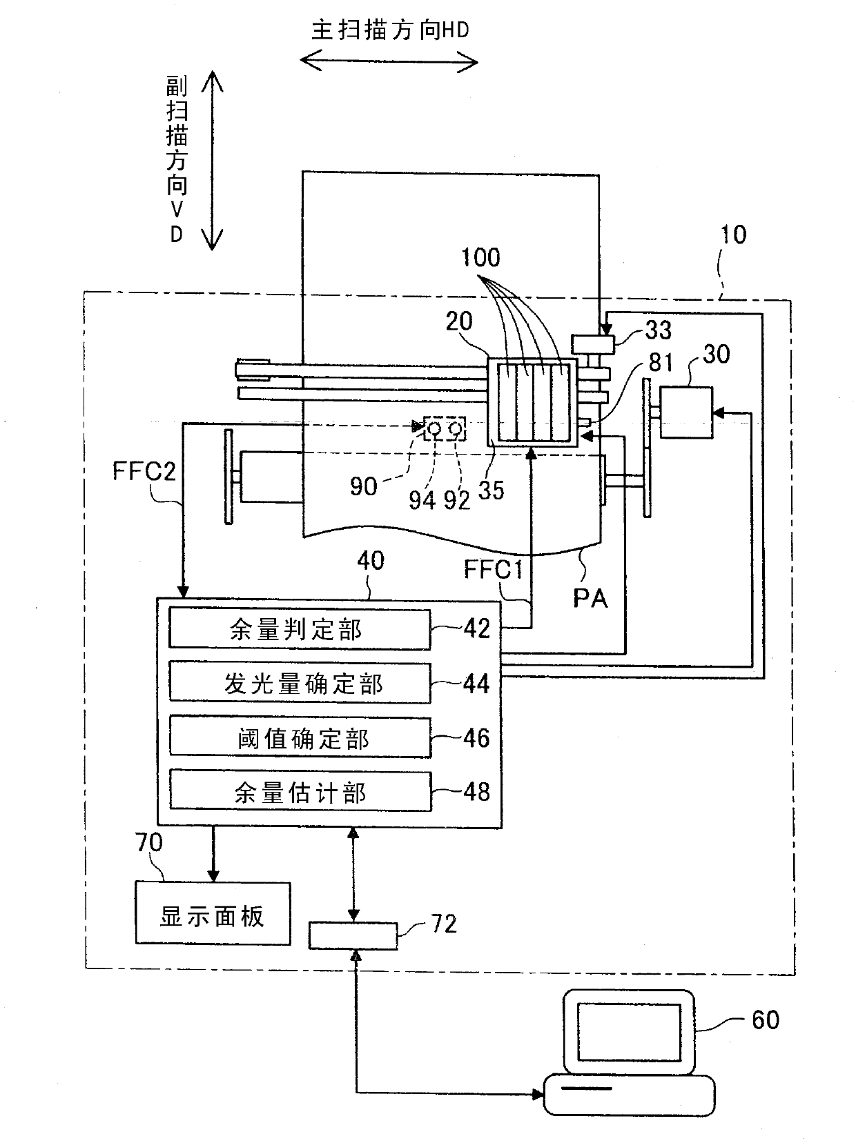
[0164] exist Figure 12 In the threshold determination processing shown, the threshold is calculated based on the bottom value corresponding to the light emission amount determined by the light emission amount determination processing. On the other hand, for example, the output voltage of the detection unit 90 corresponding to the reflected light from the reflector 81 may be set to a predetermined voltage, and the amount of light emitted from the light emitting unit 92 may be set to measure the amount of light emitted. Corresponding to the valley value to calculate the threshold. That is, the bottom value determined by the light emission amount determination processing and the bottom value used as the calculation reference of the threshold value in the threshold value determination processing may be different bottom values.

Deformed example 2

[0166] In the above-described embodiment, the light shielding film 50 is provided on the central portion of the bottom surface of the prism 170, but the light shielding film 50 may be omitted. In this case, for each ink cartridge 100, it is available at one location instead of two Figure 7 Valley values ​​shown.

Deformed example 3

[0168] In the above-described embodiments, the higher the amount of received light, the lower the output voltage of the detection unit 90 . On the other hand, the voltage output from the detection unit 90 may be increased as the amount of received light increases. In this case, all the “bottom values” described as the lowest output voltage of the detection unit 90 in the above-described embodiments can be understood as the highest “peak values” of the output voltage of the detection unit 90 . In addition, in this case, the above formula (1) can be expressed as the following formula (1b).

[0169] V2=V1×(PD2 / PD1)×(Vref2 / Vref1)…(1b)


PUM


Abstract

The invention relates to a liquid consumption device and a method. The present invention intends to provide a liquid consumption device technology capable of determining with good precision the residual state of liquid inside a liquid container mounted in the liquid consumption device. The liquid consumption device includes a liquid container, a prism, a light emitting unit, a light receiving unit and a control unit. The liquid container is configured to supply liquid to the liquid consumption device. The prism is provided to the liquid container, and configured to receive light that is made incident from outside and to emit the incident light again toward the outside according to a liquid residual state inside the liquid container. The light emitting unit is configured to radiate the light to the prism. The light receiving unit is configured to receive the light emitted from the prism. The control unit is configured to control the light emitting unit to radiate the light, and to determine the liquid residual state based on a light volume of the light received by the light receiving unit. Before the liquid residual state is determined, the control unit is configured to determine a threshold value of the liquid container for determining at least one of a light radiation volume by the light emitting part and the liquid residual state, based on a light volume of reflected light that was reflected by an outer surface of the prism and received by the light receiving unit upon radiation of the light by the light emitting unit.

Description

technical field [0001] The present invention relates to liquid consuming devices and methods. Background technique [0002] An ink cartridge, which is a detachable liquid container, is usually attached to an inkjet printing device as an example of a liquid consuming device. A prism may be included in an ink cartridge in order to optically detect the remaining state of ink inside. [0003] As for the technique of detecting remaining state of ink using a prism, for example, the printing apparatus described in Patent Document 1 uses an alignment reflector provided on a carriage to align an output of a phototransistor configured as a light receiving unit. Specifically, light is irradiated from an LED configured as a light emitting unit to the calibration reflector, the reflected light reflected by the calibration reflector is received using a phototransistor, and the LED is controlled so that the output of the phototransistor falls within a certain range. The amount of luminou...

Claims


Application Information

Patent Timeline
Patent Type & Authority Applications(China)
IPC IPC(8): B41J2/175
CPCB41J2002/17573B41J2/17566
Inventor 西原雄一
Owner SEIKO EPSON CORP
Why Eureka
Try Eureka