A liquid flow battery initial charging method and circuit

A flow battery, initial charging technology, applied in the direction of secondary battery charging/discharging, battery circuit device, circuit device, etc., can solve the problems of low degree of automation, long charging time, small capacity, etc. Safe and reliable, saving hardware cost

Active Publication Date: 2015-09-30
大连尚佳新能源科技有限公司
View PDF6 Cites 3 Cited by
  • Summary
  • Abstract
  • Description
  • Claims
  • Application Information

AI Technical Summary

Problems solved by technology

[0002] In recent years, due to the advantages of high storage capacity, long service life, excellent rechargeability, high energy conversion efficiency, and high cost performance, flow batteries have not only become a supporting energy storage device for solar and wind power generation processes, but also with the distribution The large-scale application of conventional power sources has led to more and more unstable factors in the power grid. Using energy storage batteries to shave peaks and fill valleys of distributed power sources, to store electric energy or to transform and transmit power according to system instructions is the current domestic and foreign The main method adopted is that the liquid flow battery is very suitable as an energy storage battery for a large-capacity energy storage power station due to its own advantages, making the liquid flow battery an emerging energy product for grid peak regulation, improving grid stability and ensuring grid security; but Technically, the liquid flow battery has the defect of requiring initial charging, that is, when the liquid flow battery is in a state of leaving the factory, not used for a long time, or the battery is faulty, it basically has no voltage and electric energy. In the prior art, the initial charging of the liquid flow battery is completed. The method has the disadvantages of high cost, small capacity, long charging time, not fully combining the characteristics of flow batteries, low degree of automation, and often requires manual operation. The bidirectional converter is a bidirectional converter that transfers energy between batteries and batteries. It can not only convert the DC voltage generated by the flow battery into AC voltage, but also convert the grid voltage into DC voltage. The core structure of the energy storage inverter is power conversion. The module, which also includes contactors, reactors and other components, can make full use of the structure and components of the energy storage inverter to carry out effective, convenient and intelligent initial charging of the flow battery. It is an important means to improve the service life of flow batteries and give full play to the advantages of flow batteries. At the same time, it can also save hardware costs, promote the wide application of flow batteries, and play a significant role in the development of energy storage inverters that use flow batteries as energy storage batteries. big boost

Method used


Image

  • A liquid flow battery initial charging method and circuit

Examples


Embodiment Construction

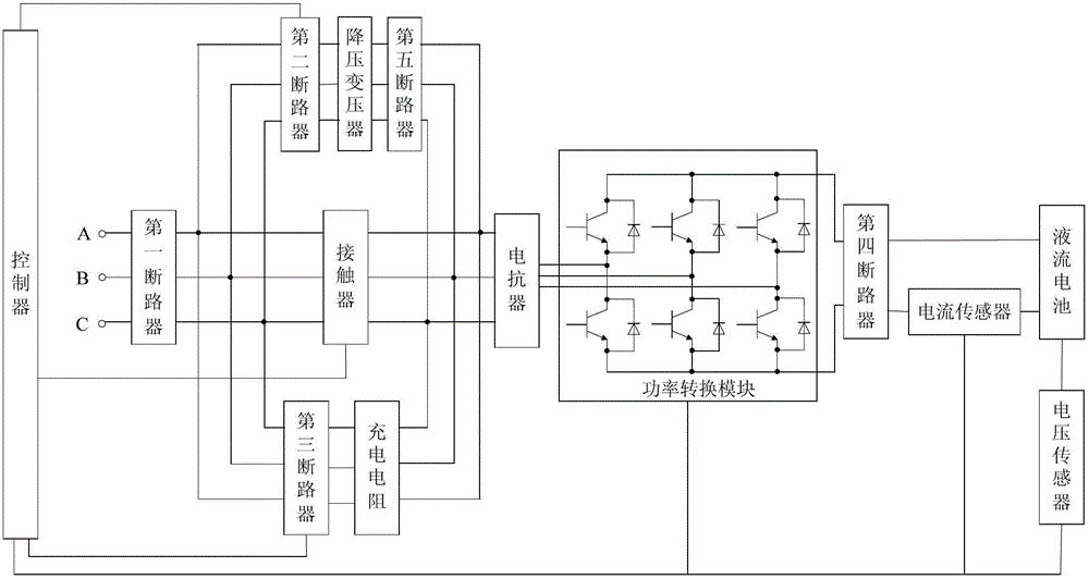
[0026] A method for initial charging of a liquid flow battery, comprising the steps of:

[0027] Step 1: Establish the initial voltage stage of the flow battery;

[0028] When the flow battery starts charging, the first circuit breaker and the fourth circuit breaker are closed, the controller controls the third circuit breaker to close, and the alternating current is transmitted to the power conversion module through the connected charging resistor and the reactor connected to the charging resistor, and the controller controls The uncontrolled rectification unit included in the power conversion module performs rectification to charge the flow battery, and when the voltage of the flow battery rises to the voltage threshold I, the controller controls the third circuit breaker to turn off;

[0029] Step 2: High current fast charging stage;

[0030] The controller controls the closing of the second circuit breaker and the fifth circuit breaker, and the alternating current is tran...


PUM


Abstract

The invention discloses an initial charging method of a flow battery and a circuit. The circuit comprises a first circuit breaker, a second circuit breaker, a third circuit breaker, a contactor, a step-down transformer, a charging resistor, an electric reactor, a power conversion module, a fourth circuit breaker and a controller, wherein an input end of the first circuit breaker is connected with three-phase alternating current; the second circuit breaker, the third circuit breaker and the contactor are respectively connected with an output end of the first circuit breaker; the step-down transformer is connected with the second circuit breaker in series; the charging resistor is connected with the third circuit breaker in series; the electric reactor is respectively connected with a secondary end of the step-down transformer, the contactor and the charging resistor; an input end of the power conversion module is connected with the electric reactor; an input end of the fourth circuit breaker is connected with an output end of the power conversion module; and the controller is respectively connected with the contactor, the second circuit breaker, the third circuit breaker and the power conversion module. According to the initial charging method of the flow battery and the circuit disclosed by the invention, initial charging of the flow battery can be realized by sufficiently utilizing a self structure of an energy-storing converter, so that the hardware cost is saved and different charging paths can be completely and automatically switched; and therefore, the efficient, convenient and intelligent initial charging of the flow battery can be realized.

Description

technical field [0001] The invention relates to an initial charging method and circuit of a liquid flow battery. Background technique [0002] In recent years, due to the advantages of high storage capacity, long service life, excellent rechargeability, high energy conversion efficiency, and high cost performance, flow batteries have not only become a supporting energy storage device for solar and wind power generation processes, but also with the distribution The large-scale application of conventional power sources has led to more and more unstable factors in the power grid. Using energy storage batteries to shave peaks and fill valleys of distributed power sources, to store electric energy or to transform and transmit power according to system instructions is the current domestic and foreign The main method adopted is that the liquid flow battery is very suitable as an energy storage battery for a large-capacity energy storage power station due to its own advantages, maki...

Claims


Application Information

Patent Timeline
Patent Type & Authority Patents(China)
IPC IPC(8): H01M10/44H02J7/10
CPCY02E60/10
Inventor 蒲延洲许明夏
Owner 大连尚佳新能源科技有限公司
Why Eureka
Try Eureka