
Closed loop testing method of power plant side automatic voltage control system

A closed-loop testing and control system technology, applied in the direction of electrical testing/monitoring, etc., can solve the problems of economical operation of the power system and the far-reaching goals of reliable power supply.

Inactive Publication Date: 2013-08-14
SHANGHAI UNIVERSITY OF ELECTRIC POWER
View PDF2 Cites 10 Cited by
  • Summary
  • Abstract
  • Description
  • Claims
  • Application Information

AI Technical Summary

Problems solved by technology

This adjustment method can only ensure the voltage of some nodes and some nodes is qualified, but it is far from the goal of economical operation and reliable power supply of the power system.

Method used


Image

  • Closed loop testing method of power plant side automatic voltage control system
  • Closed loop testing method of power plant side automatic voltage control system
  • Closed loop testing method of power plant side automatic voltage control system

Examples


Embodiment 1

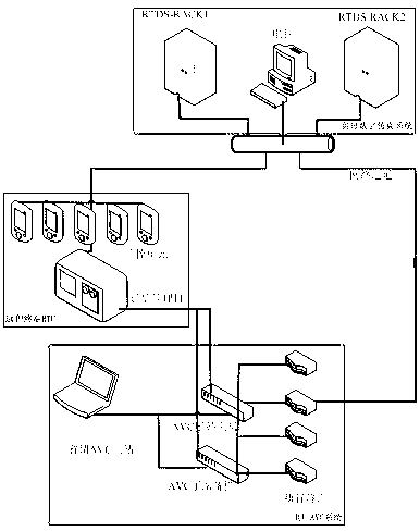
[0043]Embodiment 1. Pulse width setting test of the reactive power regulating device of the unit: This test is one of the parameter setting tests. In this test, important parameters such as unit signal output interval, maximum signal width, minimum signal width and slope in "reactive power output setting" are set by adjusting the output pulse width of the AVC substation, so as to accumulate experience for field tests and parameter tuning.

Embodiment 2

[0044] Embodiment 2. Reactive power distribution adjustment performance test between units: This test is one of the basic function tests. Set the "busbar voltage regulation" mode of the AVC system to test the rationality of the reactive power distribution of each unit during the adjustment process of the AVC substation, that is, test four distribution methods, such as: equal power factor reactive power distribution, equal margin reactive power distribution , equal-capacity reactive power distribution, reactive power average distribution, and check the distribution effect of various reactive power distribution methods.

Embodiment 3

[0045] Embodiment 3. Unit reactive power reverse modulation test: This test is one of the basic function tests. Test the ability of the AVC system to adjust the reactive power out-of-limit inversion and allocate the reactive power reasonably. First set the "busbar voltage regulation" mode, the master station sends an instruction to demagnetize until the reactive power of the unit exceeds the lower limit, and check the reactive power reverse regulation process of the AVC sub-station device. Or, the master station sends an instruction to increase the magnetization until the reactive power of the unit exceeds the upper limit, and check the reactive power inversion process of the AVC sub-station device.


PUM


Abstract

The invention relates to a closed loop testing method of a power plant side automatic voltage control (AVC) system. A closed loop testing system established on a power plant side AVC system comprises a real-time digital simulation system, the power plant side AVC system and a remote terminal RTU (remote terminal unit), wherein the real-time digital simulation system models a simulation power plant actual power system and simulates a power generation system to enter a corresponding running state; the real-time digital simulation system outputs a control signal to the remote terminal RTU; the control signal is processed and converted by the remote terminal RTU; the data is sent to the power plant side AVC system; the power plant side AVC system transmits the actual control signal to a corresponding simulation element of a system platform model in the real-time digital simulation system; and after a central control system model simulates the actual control signal, the control signal is output, a closed loop is formed, and closed loop testing is realized. The functions of the power plant side AVC system are tested in real time off line, the method has an important guidance effect on the establishment of unified indexes of the power plant side AVC system, and a very good solution is provided for access test on the power plant side AVC system.

Description

technical field [0001] The invention relates to a power testing technology, in particular to a closed-loop testing method for an automatic voltage control system on a power plant side. Background technique [0002] Reactive power optimization and compensation of power system is an important part of safe and economical operation of power system. Through reasonable configuration of reactive power sources and compensation of reactive loads, not only can the voltage level be maintained, the stability of power system operation can be improved, but also network losses can be reduced, enabling the power system to operate safely and economically. In the traditional voltage control management mode, the generator reactive power and high-voltage bus voltage of the power plant are mainly adjusted manually by the on-duty personnel of each power plant according to the requirements of system scheduling. This adjustment method can only ensure that the voltage of some time periods and some ...

Claims


Application Information

Patent Timeline
Patent Type & Authority Applications(China)
IPC IPC(8): G05B23/02
Inventor 范宏周德生潘爱强陈超计圣凯丁会凯
Owner SHANGHAI UNIVERSITY OF ELECTRIC POWER
Learn More