Soft-wing unmanned aerial vehicle with automatic defogging function

An unmanned aerial vehicle and fog elimination technology, applied in the field of soft-wing unmanned aerial vehicles, can solve the problems of low drone payload, complex take-off and landing of drones, and high cost, so as to improve the microclimate of disaster relief areas and improve road traffic. Environment, the effect of eliminating dense fog in the airport

Inactive Publication Date: 2015-08-12
武汉南沙工贸有限公司
View PDF6 Cites 1 Cited by
  • Summary
  • Abstract
  • Description
  • Claims
  • Application Information

AI Technical Summary

Problems solved by technology

However, the payload of the UAV is relatively low (generally, the payload is 10-15kg), the carrying capacity of one flight operation is small, and the area for defogging is small. Moreover, the take-off and landing of the UAV are relatively complicated and costly
[0008] The third is ground spreading: this method requires setting up multiple catalyst spreading points on the ground, and spreading the catalyst at a height of several meters above the ground, but this method will be affected by wind direction and wind speed
Moreover, setting multiple catalyst spreading points in the fog zone consumes a huge amount of manpower and material resources
Especially on the expressway, it is necessary to install an instrument for spreading catalyst not far from the roadside along the way, and the cost is very high.

Method used


Image

  • Soft-wing unmanned aerial vehicle with automatic defogging function
  • Soft-wing unmanned aerial vehicle with automatic defogging function
  • Soft-wing unmanned aerial vehicle with automatic defogging function

Examples


Embodiment Construction

[0041] The present invention is further described by the following examples.

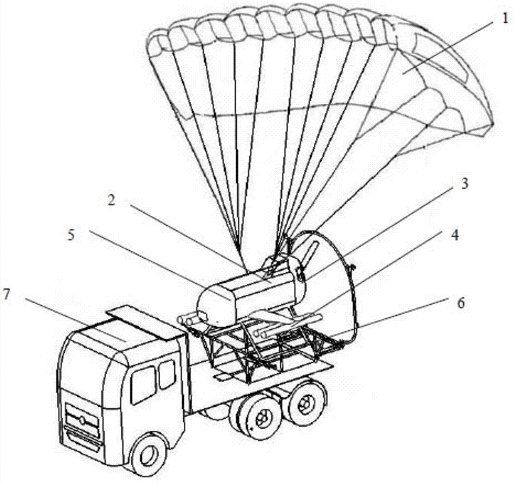
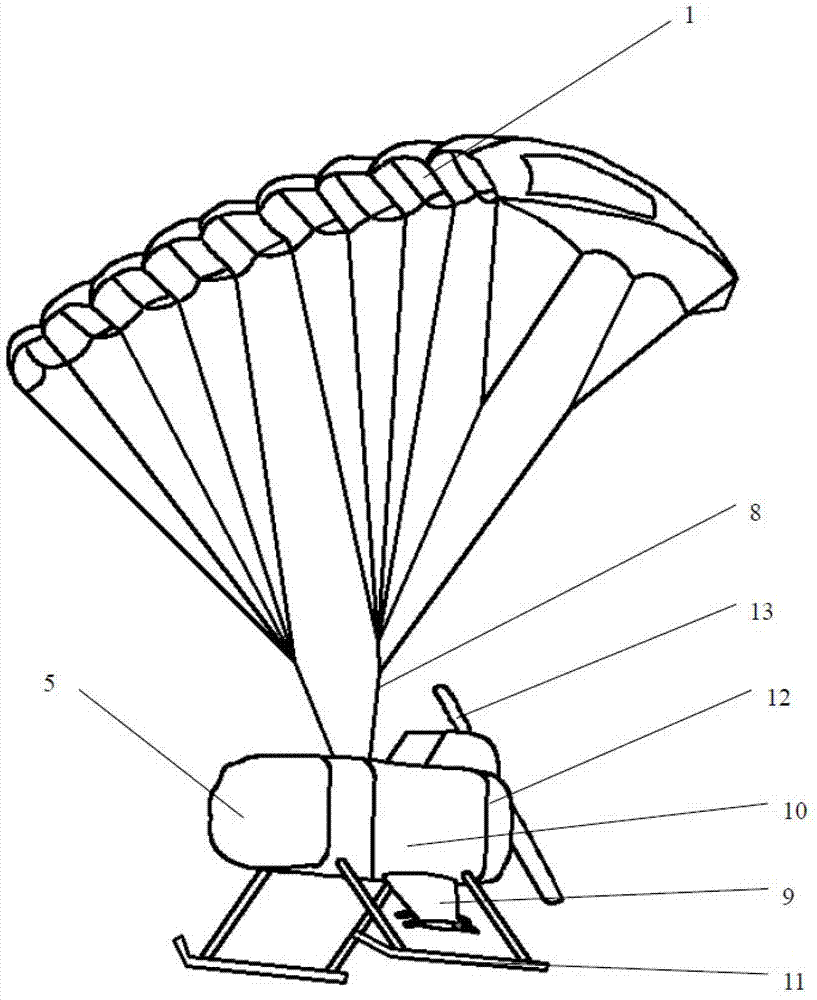
[0042] figure 1 It is a schematic diagram of the appearance of the soft-wing unmanned aerial vehicle with automatic defogging function of this embodiment, figure 2 It is a structural schematic diagram of the soft-wing unmanned aerial vehicle with automatic defogging function of this embodiment. see figure 1 and figure 2, The soft-wing UAV with automatic defogging function in this embodiment includes: flexible ram parafoil 1, structural cabin body 2, power system 3, defogging equipment and control system 5; flexible ram parafoil 1 provides lift to the system.

[0043] The lower part of the flexible stamping parafoil 1 is connected to the structural cabin body 2 through the parachute 8; the structural cabin body 2 is equipped with a control system 5 and a built-in defogging device 14, and a power system 3 is installed at the rear.

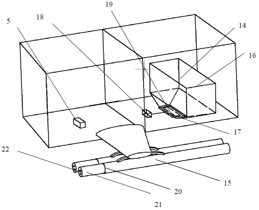
[0044] The structural cabin body 2 mainly includes a cabin body...


PUM


Abstract

The invention provides a soft-wing unmanned aerocraft with an automatic fog dispersal function. The soft-wing unmanned aerocraft comprises a flexible stamping parawing, a structure cabin body, a power system, fog dispersal equipment and a control system, wherein the fog dispersal equipment comprises internal fog dispersal equipment and external fog dispersal equipment for simultaneously or respectively scattering an antifogging agent; the internal fog dispersal equipment is arranged in the structure cabin body, and the external fog dispersal equipment is arranged outside the structure cabin body; the internal fog dispersal equipment is composed of a scattering and throwing cabin, a flashboard, a steering engine and a throwing port; the external fog dispersal equipment is composed of fixing frames, scattering and throwing cylinders and exciting electrodes; and the fog dispersal equipment also comprises detection equipment. The soft-wing unmanned aerocraft provided by the invention has the beneficial effects that the operation is safe and reliable, the control is easy, and the carrying capacity is large; the distance range of flying fog dispersal can reach 200 kilometers through remote control and autonomous navigation; the cost is cheap, and the operation is simple and practicable; and the application range is wide, and the soft-wing unmanned aerocraft is suitable for situations needing local fog dispersal, such as improvements on highway traffic environments, dispelling of thick fog of an airport, and change of microclimate of a disaster relief region.

Description

technical field [0001] The invention relates to the field of unmanned aerial vehicles, in particular to a soft-wing unmanned aerial vehicle with an automatic defogging function. Background technique [0002] Both drones and unmanned aerial vehicles are unmanned, but there are substantial differences. UAVs have fixed wings and are mostly used for military purposes such as high-altitude reconnaissance and attacking ground targets, and are rarely used for civilian purposes. [0003] In order to meet various needs, people have researched and manufactured various unmanned aerial vehicles. The invention patent ZL 93202125.5 (authorized announcement number CN2204774Y) of the Airborne Forces Research Institute of the Chinese People's Liberation Army discloses a powered flying flexible stamped parafoil, which is used for flight performances, advertising, frontier patrols and recreational flights. In addition, in the Chinese utility model patent ZL201220565967.0 (authorized announcem...

Claims


Application Information

Patent Timeline
Patent Type & Authority Patents(China)
IPC IPC(8): B64C31/036B64D1/16B64F1/10G01C21/00
Inventor 孙晓伟彭俊生薛富利郭海军王文凯贺应平祝远程龚松洁毛威
Owner 武汉南沙工贸有限公司
Why Eureka
Try Eureka