Coating implement and coating liquid box
A technology for coating liquid and utensils, applied to writing utensils, printing, other ink pens, etc., can solve problems such as ink consumption
- Summary
- Abstract
- Description
- Claims
- Application Information
AI Technical Summary
Problems solved by technology
Method used
Image


Examples
no. 1 approach )
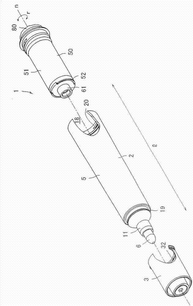
[0172] The applicator 1 of the first embodiment of the present invention is a marker pen (marker pen) for a whiteboard, such as figure 1 , figure 2 As shown, an applicator main body 2 , a cover member 3 , and an ink cartridge 50 (coating liquid ink cartridge) are included.
[0173] Such as image 3 As shown, the applicator main body 2 has: a main body cylinder (tube part) 5 ; an inner cotton 6 ; a relay core 7 ; and a pen tip member (applicator part) 8 .
[0174] The main body cylinder 5 is a hollow body in which a space is provided over the entirety in the longitudinal direction l. The main body barrel 5 is roughly divided into a front plug portion 11 , an inner cotton storage portion 12 , and an ink tank mounting portion 15 in order from the tip end side (the pen tip member 8 side).
[0175] The front plug portion 11 is a portion where the pen tip member 8 is fixed, and the appearance of the front plug portion 11 is formed in a shape that becomes thinner toward the front...
no. 2 approach )
[0270] Next, a second embodiment of the present invention will be described below. However, the same components as those in the first embodiment are given the same reference numerals, and description thereof will be omitted.
[0271] The shape of the fitting portion of the ink cartridge is different between the applicator 100 of the second embodiment and the applicator 1 of the first embodiment.
[0272] Hereinafter, the fitting portion 180 of the ink cartridge 150 will be described.
[0273] like Figure 17 As shown, the fitting portion 180 is rotationally symmetrical about five turns around the rotation axis n.
[0274] Here, the fitting part 80 which is the characteristic part of this invention is demonstrated in more detail.
[0275] In this embodiment, the central portion is also recessed compared to its periphery. In addition, it can also be said that the protrusions and the holes are arranged in line on the circumference.
[0276] like Figure 18 As shown, the fit...
no. 3 approach )
[0292] Next, a third embodiment of the present invention will be described below. In addition, the same code|symbol is attached|subjected to the same component as 1st Embodiment and 2nd Embodiment, and description is abbreviate|omitted.
[0293] In this embodiment, the central portion is also recessed compared to its periphery. In addition, it can also be said that the protrusions and the holes are arranged in line on the circumference.
[0294] The shape of the fitting portion of the ink cartridge is different between the applicator 200 of the third embodiment and the applicator 1 of the first embodiment.
[0295] Hereinafter, the fitting portion 280 of the ink cartridge 250 will be described.
[0296] Such as Figure 20 , Figure 21 As shown, the fitting portion 280 has a plurality of convex portions 285 and a plurality of concave portions 286 .
[0297] The fitting portion 280 is rotationally symmetrical about two turns around the rotation axis n (central axis).
[0298...
PUM
| Property | Measurement | Unit |
|---|---|---|
| Length | aaaaa | aaaaa |
| Length | aaaaa | aaaaa |
Abstract
Description
Claims
Application Information
 - Generate Ideas
- Intellectual Property
- Life Sciences
- Materials
- Tech Scout
- Unparalleled Data Quality
- Higher Quality Content
- 60% Fewer Hallucinations
Browse by: Latest US Patents, China's latest patents, Technical Efficacy Thesaurus, Application Domain, Technology Topic, Popular Technical Reports.
© 2025 PatSnap. All rights reserved.Legal|Privacy policy|Modern Slavery Act Transparency Statement|Sitemap|About US| Contact US: help@patsnap.com