
Anti-poking angle spring lock

A marble lock and angle technology, applied in the field of locks, can solve problems such as inability to reset, and achieve the effect of improving the anti-dialing performance.

Inactive Publication Date: 2013-07-24
中山市实力锁业有限公司
View PDF10 Cites 2 Cited by
  • Summary
  • Abstract
  • Description
  • Claims
  • Application Information

AI Technical Summary

Problems solved by technology

However, it still has the following disadvantages: since the side pins always have a tendency to move downward under the elastic force of the spring or under the repulsive force of the magnet or under the action of gravity, as long as the dimples on the angle pins are aligned with the side pin holes one by one Alignment, the side pins will be automatically inserted into the recess to lock the angle pins so that they cannot be reset, that is, there is a linkage relationship between the side pins and the angle pins

Method used


Image

  • Anti-poking angle spring lock
  • Anti-poking angle spring lock
  • Anti-poking angle spring lock

Examples


Embodiment Construction

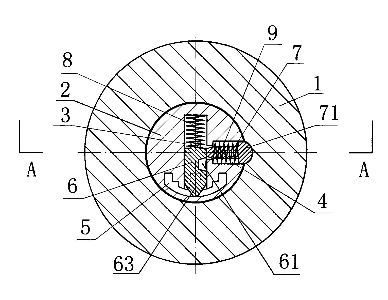
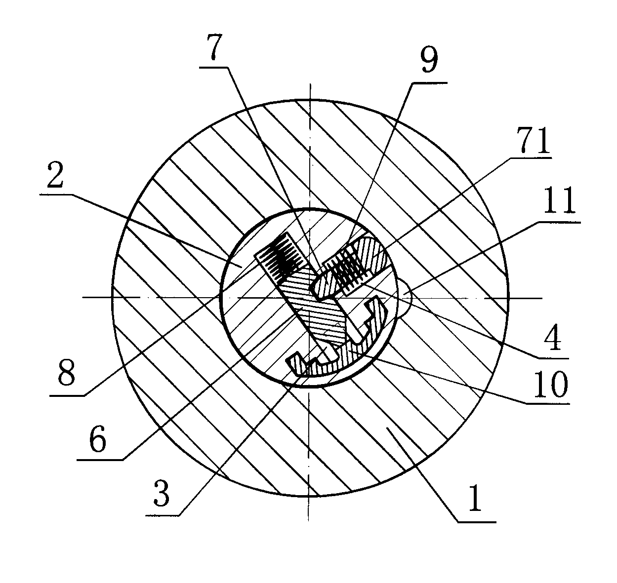
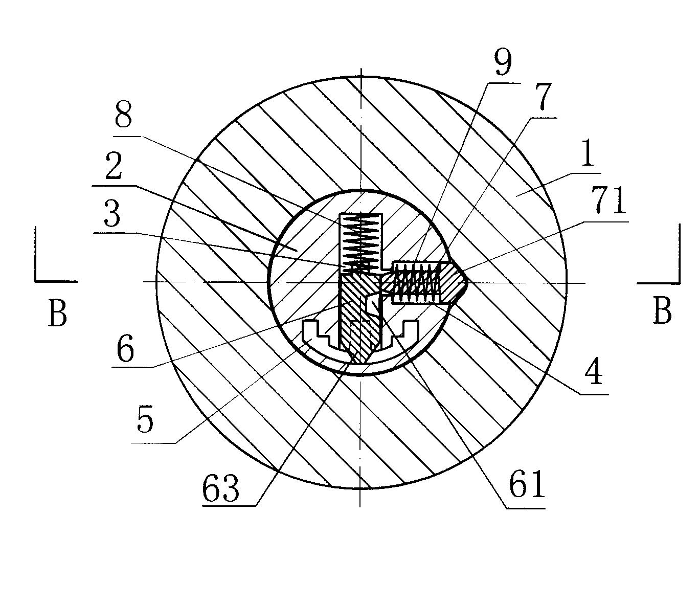
[0020] Referring to Figures 1 to 3, the anti-dialing angle tumbler lock of Embodiment 1 is composed of a lock body 1 and a lock cylinder 2 arranged in the lock body 1, wherein the lock cylinder 2 is provided with five groups along the axial direction of the lock cylinder 2. Arranged pinholes, each group of pinholes is composed of angle pinholes 3 and side sliding pinholes 4 arranged along the radial direction of the lock core 2 and the axes are perpendicular to each other, wherein the angle pinholes 3 are formed by the center of the lock core 2 The axis is formed by extending radially to both sides, one end of which communicates with the axial keyhole 5 located at the edge of the lock core 2, and the other end is a closed end; The radial extension of the lock core 2 is formed, one end of which communicates with the angle pin hole 3 , and the other end penetrates the outer wall of the lock core 2 .

[0021] Referring to Figures 1 to 5, the angle pinhole 3 is provided with an a...


PUM


Abstract

The invention discloses an anti-poking angle spring lock, comprising a lock cylinder and a lock body, wherein a plurality of groups of marble holes which are arrayed along the axial direction of the lock cylinder are arranged in the lock cylinder, each group of marble holes consist of an angle marble hole and a sideslipping marble hole which are communicated and are arranged along the radial direction of the lock cylinder, each angle marble hole is internally provided with an angle marble and a reset spring, each sideslipping marble hole is internally provided with sideslipping marbles, one end, far away from the corresponding angle marble hole, of each sideslipping marble is provided with a locking head with an inclined surface, the lock body is provided with locking cavities, matched with the inclined surfaces of the locking heads, on the matched surface of the lock body and the lock cylinder, and locking springs are used for trying to enable the locking heads on the sideslipping marbles to abut against the interiors of the locking cavities all the time. The anti-poking angle spring lock has the advantages of high anti-poking performance and is suitable for being made into various locks, such as a door lock, a window sash lock, a car lock and a furniture lock.

Description

technical field [0001] The invention relates to a lock, in particular to an angle tumbler lock. Background technique [0002] A common pin lock consists of a lock cylinder, a lock body, a pin and a spring. Among them, the lock core and the lock body are provided with several groups of radial pinholes, which communicate with the keyhole on the lock core. Each pinhole There are two marbles in the hole, and the spring is arranged in the pin hole and is located at one end of the lock body. In the natural state, the spring presses the two pins against the key hole. At this time, the two pins in each pin hole The contact surface is located in the lock cylinder, and the lock cylinder cannot be rotated; when the matching key is inserted, the ends of the pins in the lock core are against the corresponding alveoli of the key, so that the contact surface of the two pins in each pin hole It just coincides with the mating surface between the lock cylinder and the lock body, and the lock...

Claims


Application Information

Patent Timeline
Patent Type & Authority Applications(China)
IPC IPC(8): E05B27/06E05B15/14
Inventor 麦明显全波
Owner 中山市实力锁业有限公司
Learn More