Lightning arrester device capable of being dismounted and installed in charged state

A technology for lightning arresters and live parts, which is applied in the field of electrified detachable lightning arrester devices, and can solve the problems of high labor intensity and low work efficiency for maintenance workers

Inactive Publication Date: 2013-07-10
冯长富
View PDF7 Cites 4 Cited by
  • Summary
  • Abstract
  • Description
  • Claims
  • Application Information

AI Technical Summary

Problems solved by technology

In addition, to disassemble and assemble the zinc oxide arrester, workers must climb up the pole to operate, the labor intensity of the maintenance workers is high, and the work efficiency is low

Method used


Image

  • Lightning arrester device capable of being dismounted and installed in charged state
  • Lightning arrester device capable of being dismounted and installed in charged state
  • Lightning arrester device capable of being dismounted and installed in charged state

Examples


Embodiment 1

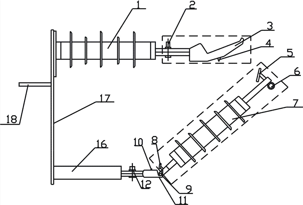
[0015] Embodiment 1 When the "chargeable detachable lightning arrester device" is running on the power grid, it needs to be removed, and at this time the power line cannot be powered off. The staff stands on the ground and uses a qualified insulating operating rod. The movable cover 3 of the charged end is bumped upwards, and the wedge 22 in the movable cover causes the movable contact 5 to separate from the static contact 4 due to displacement, and the removable assembly falls. The detachable assembly that falls this moment hangs in the rotating shaft bracket groove 11, and now the operator passes in the operating ring 6 with 24 forks at the top of the operating rod again, and the assembly is taken off.

Embodiment 2

[0016] Example 2 After replacing the qualified lightning arrester on the detachable assembly, use the 24 forks on the top of the operating rod to penetrate into the operation ring 6, and put the rotating shaft 9 of the detachable assembly into the rotating bracket of the grounding end 13 After entering the groove 11, forcefully bump the movable contact 5 of the detachable assembly into the movable cover 3 at the end of the charged component, so that the movable contact 5 enters the cover and the wedge 22 is stuck—the elastic force of the spring 19 on the movable cover 3 effect. At this time, the static contact 4 of the electrified assembly is in close contact with the movable contact 5, and the movable contact 9 at the lower end of the detachable assembly also rotates and moves forward to closely contact with the static contact 10 to conduct. Complete the operation of installing the lightning arrester when it is live.


PUM


Abstract

The invention provides a lightning arrester device capable of being dismounted and installed in a charged state. The lightning arrester device capable of being dismounted and installed in a charged state is composed of an insulation support body, a charged part assembly, a detachable assembly, a grounding assembly, a grounding support body, a base and a support strap iron body. The charged part assembly is composed of a fixed contact movable cover and a power source binding post, and the charged part assembly is fixedly connected with the insulation support body as a whole through a bolt. The detachable assembly is composed of a charged end moving contact, an operating ring, a lightning arrester, a grounding end moving contact and a rotating shaft. The grounding assembly is composed of a grounding end fixed contact, a support groove and a bolt hole formed in the support groove, and the grounding support body and a grounding end assembly are fixedly connected as a whole through bolts. The insulation support body and the grounding support body are respectively fixed at two ends of the base through bolts to form the whole lightning arrester device capable of being dismounted and installed in a charged state. The base is fixed on a pole cross arm through the support strap iron body. According to the lightning arrester device capable of being charged in dismounting, workers can securely dismount and install the lightning arrester on the ground under the premise that power (a power grid) is not cut. Therefore, reliability of power supply is improved, and practicability is strong.

Description

technical field [0001] The invention relates to a brand-new installation of a lightning arrester for a power grid and a power generation system, in particular to a lightning arrester device that can be disassembled when charged. Background technique [0002] There are two types of lightning protection facilities for power grids and transmission systems, one is lightning rods and wires to prevent direct lightning damage, and the other is lightning arresters to prevent induced overvoltages—the zinc oxide arresters are commonly used at present, connected to 10KV lines On the protection of distribution transformers; important power equipment such as cable heads, transformers, pole switches, etc., to avoid damage to them due to the strong induced overvoltage generated on the line when thunderstorms occur in the sky. However, since the zinc oxide arrester is firmly connected to the 10KW or 35KW line, once the arrester fails during operation, or an accident, or an annual preventive...

Claims


Application Information

Patent Timeline
Patent Type & Authority Applications(China)
IPC IPC(8): H02G13/00
Inventor 冯长富
Owner 冯长富
Why Eureka
Try Eureka