
A microseismic monitoring system and its installation method

A microseismic monitoring and microseismic sensor technology, which is applied in the direction of measuring devices, seismology, geophysical measurement, etc., can solve the problems of cumbersome operation, manpower consumption, and affecting the sensing accuracy and sensitivity of microseismic sensors, so as to achieve good sensing accuracy and sensitivity , The effect of facilitating construction and layout

Active Publication Date: 2016-03-23
CHINA UNIV OF MINING & TECH (BEIJING)
View PDF4 Cites 0 Cited by
  • Summary
  • Abstract
  • Description
  • Claims
  • Application Information

AI Technical Summary

Problems solved by technology

The existing arrangement of microseismic sensors is not only cumbersome to operate and consumes manpower, but also constantly removed and installed, which will greatly affect the sensing accuracy and sensitivity of the microseismic sensors

Method used


Image

  • A microseismic monitoring system and its installation method

Examples


Embodiment

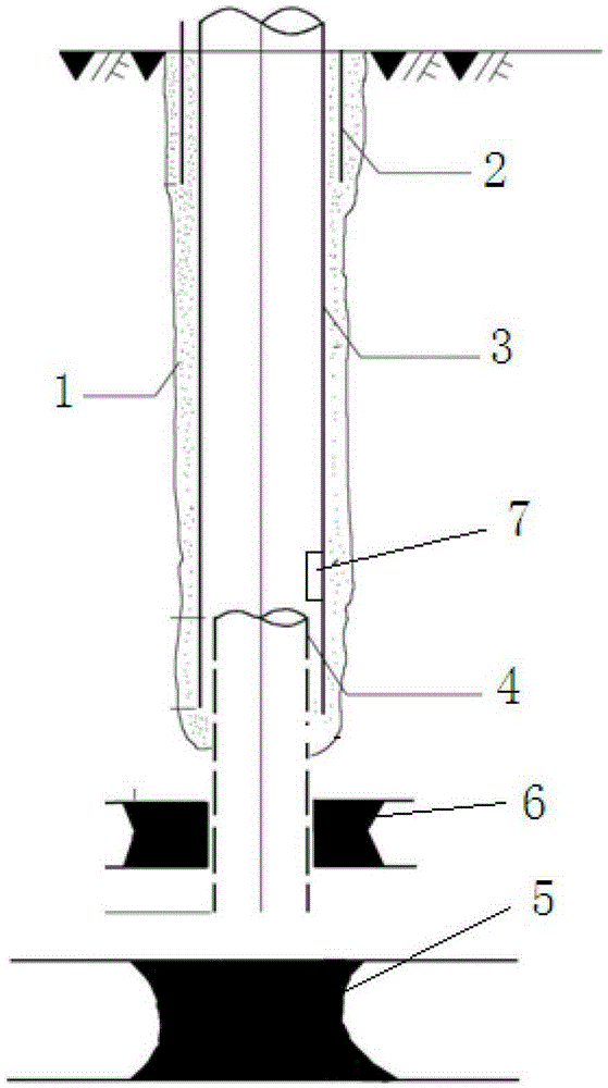
[0036] Such as figure 1As shown, the surface pre-drainage hole includes a cementing 1, a surface casing 2 is arranged at the position of the cementing 1 opening on the ground, a technical casing 3 is sleeved in the surface casing 2, and a technical casing 3 The lower part is set with a gas production casing 4; the gas production casing 4 passes through the upper adjacent layer 5 to reach a position near the top of the coal seam 6; the microseismic sensor 7 is installed on the inner wall of the technical casing 3 and is close to the gas production casing 4 position.


PUM


Abstract

An embodiment of the invention discloses a micro-seismic monitoring system and a method for mounting the same, and relates to the field of micro-seismic monitoring technology. The micro-seismic monitoring system and the method are characterized in that micro-seismic sensors of the micro-seismic monitoring system are mounted in perforated gas holes on the ground. The micro-seismic monitoring system and the method have the advantages that the micro-seismic sensors can be conveniently arranged, and are assuredly high in sensing precision and sensitivity. The micro-seismic monitoring system and the method are applicable to micro-seismic monitoring for high-gas drainage mines.

Description

technical field [0001] The invention relates to a microseismic monitoring system, in particular to the installation of a microseismic sensor in the microseismic monitoring system. Background technique [0002] Coal mine dynamic impact rock pressure disaster is a kind of mine earthquake induced by mining, which not only causes damage to shafts, personnel injuries, and damage to ground buildings, but also causes gas and coal dust explosions. Due to the complexity, diversity and suddenness of the time, place, region, and earthquake source of such disasters, its prevention, especially prediction, is a worldwide problem. [0003] The existing microseismic monitoring system includes a microseismic sensor installed on the underground working face, a signal acquisition station, and a ground center station; the signal acquisition station collects the microseismic signal sensed by the microseismic sensor, and converts the collected microseismic signal into a digital signal for transmi...

Claims


Application Information

Patent Timeline
Patent Type & Authority Patents(China)
IPC IPC(8): G01V1/20G01V1/00
Inventor 张毅杨国梁刘康郭东明宋俊生
Owner CHINA UNIV OF MINING & TECH (BEIJING)
Learn More