Transmitter with preassembled synchronizing rings

A technology of transmitter and synchronizing ring, applied in the direction of intermeshing clutches, clutches, mechanical drive clutches, etc., can solve the problems of complex parts and huge structures, and achieve the effect of simple structure and compact structure

Active Publication Date: 2013-06-12
HOERBIGER ANTRIEBSTECHN HLDG
View PDF6 Cites 8 Cited by
  • Summary
  • Abstract
  • Description
  • Claims
  • Application Information

AI Technical Summary

Problems solved by technology

[0004] The disadvantage of the known synchronization components is the very complex and locally very bulky structures

Method used


Image

  • Transmitter with preassembled synchronizing rings
  • Transmitter with preassembled synchronizing rings
  • Transmitter with preassembled synchronizing rings

Examples


Embodiment Construction

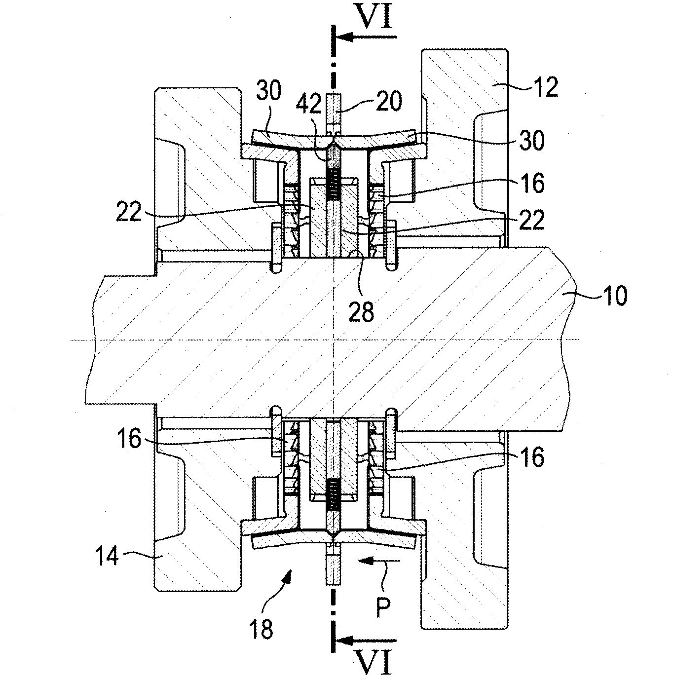
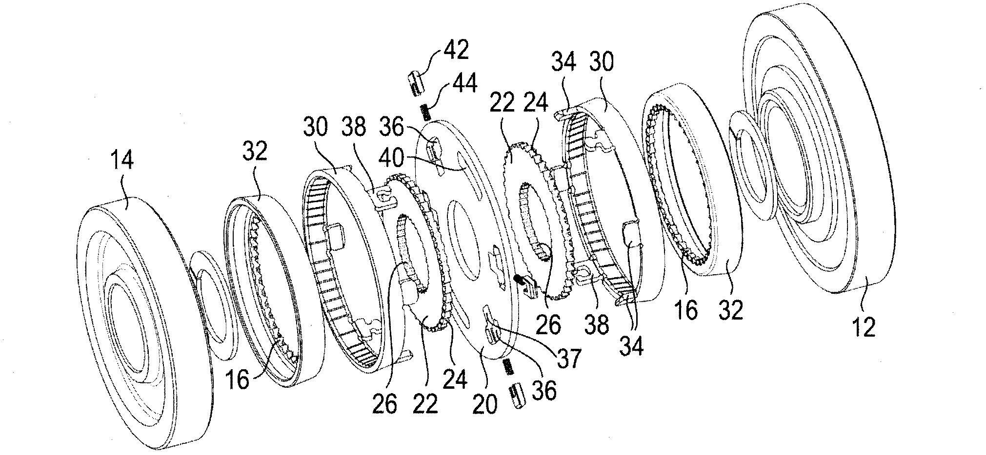
[0056] The following will refer to Figure 1 to Figure 8 The basic structure of a synchronization assembly for a manual transmission in which the transmitter according to the first embodiment is used is described.

[0057] The transmission comprises a gear shaft 10 on which two transmission gears 12, 14 are arranged. The two speed change gears 12, 14 are in the form of movable gears, ie they can rotate relative to the gear shaft. Clutch teeth 16 are connected to each speed change gear 12, 14 for common rotation therewith.

[0058] A transmitter 18 is arranged between the two transmission gears 12 , 14 , here the transmitter 18 is formed by a transmitter disk 20 and two clutch disks 22 . Two clutch disks 22 are arranged on either side of the transmitter disk 20 and have external toothing 24 and internal toothing 26 . The outer teeth 24 are made complementary to the clutch teeth 16 and the inner teeth 26 mesh with the pinion shaft teeth 28 . Accordingly, the clutch disc 22 i...


PUM


Abstract

The invention relates to transmitter (18) for a synchronizing assembly of a transmission, comprising a pressure piece (42), a spring (44; 84) that interacts with the pressure piece (42), and at least one synchronizing ring (30), said pressure piece (42) being acted upon by the spring (44) such that the transmitter (18) can transmit a pre-synchronizing force onto the synchronizing ring (30) in the axial direction.

Description

technical field [0001] The invention relates to a transmitter for a synchronization assembly of a manual transmission. Background technique [0002] In manual transmissions, especially for motor vehicles, a synchronizing assembly is used to create a connection which prevents relative rotation between a gear shaft and a transmission gear (or a bull gear arranged as a movable gear on the gear shaft). During the first step of the shifting process, the synchronization assembly ensures that the speed of the transmission gear to be shifted is adjusted to the speed of the gear shaft. Then in a second step, a connection for co-rotation of the gear shaft with the transmission gear is created. Then the corresponding gear is changed. [0003] It is generally known that a synchronizing assembly includes, as essential components, a synchronizing hub, a thrust piece accommodated therein, a synchronizing ring, and a shift sleeve. When the shift sleeve is actuated, a synchronizing ring i...

Claims


Application Information

Patent Timeline
Patent Type & Authority Applications(China)
IPC IPC(8): F16D23/06
CPCF16D23/06F16D23/0606F16D2023/0618F16D2023/0631F16D23/00F16D11/14
Inventor 于尔根·宾德尔托马斯·施内泽彼得·埃希特勒米夏埃尔·克尔策彼得·克拉默
Owner HOERBIGER ANTRIEBSTECHN HLDG
Why Eureka
Try Eureka