Steam exhausting cylinder of axially-exhausting steam turbine unit
A technology of steam turbine unit and exhaust cylinder, applied in the field of exhaust cylinder, can solve the problems of exhaust steam energy loss and high cost, achieve the effect of saving construction cost, meeting design requirements, and reducing three-dimensional space
- Summary
- Abstract
- Description
- Claims
- Application Information
AI Technical Summary
Problems solved by technology
Method used
Image
Examples
specific Embodiment approach 1
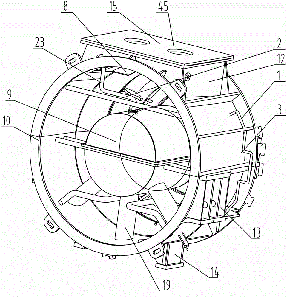
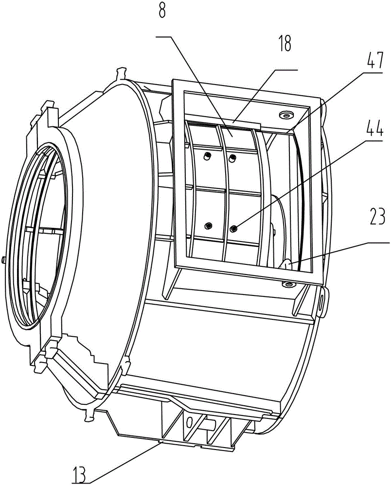
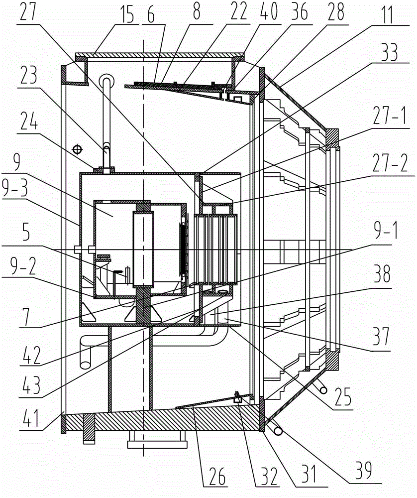
[0007] Specific implementation mode one: combine Figure 1-Figure 7 Describe this embodiment, an exhaust cylinder of an axial exhaust steam turbine unit, the exhaust cylinder includes a bearing box assembly 9, and the exhaust cylinder also includes a water spray mechanism 1, a smoke exhaust mechanism 2, an exhaust cylinder housing 3, The oil circuit mechanism 4, the exhaust steam diversion and expansion mechanism 6 and the exhaust cylinder seal body mechanism 7, the exhaust steam diversion and expansion mechanism 6 includes a second flange 28, a shroud 25 and two semi-conical diffuser guides. Flow tube 26, exhaust cylinder seal body mechanism 7 includes seal housing 27, high-pressure steam inlet pipe 37, micro-negative pressure steam extraction pipe 38, two first fixed plates 34 and two second fixed plates 35, bearing box The assembly 9 includes a bearing seat 9-1 with bearings installed, a bearing box 9-2, a sixth flange 33 and a bearing box shield 9-3; A tapered cylinder, t...
specific Embodiment approach 2
[0008] Specific implementation mode two: combination Figure 1-Figure 7 Describe this embodiment, an exhaust cylinder of an axial exhaust steam turbine unit, the exhaust cylinder housing 3 includes an arc-shaped hanging plate 8, a rectangular frame body 12, a rectangular cover plate 15, a deflector plate 22, and a third flange 29. Fourth flange 31, fixed arc plate 40, support arc plate 36, seventh flange 41, two semicircular shells 10, two support seats 13, two support frames 14, two semi-conical Shell 11, two arc-shaped channel steels 32, three supporting round pipes 19 and four blocking plates 46, two semicircular shells 10 are fastened to form a circular shell, and the inner wall of the semicircular shell 10 The inner diameter small ends of the two semicircular shells 10 are sealed and fixed to the side of the fourth flange 31 close to the inner circle, and the large inner diameter ends of the two semicircular shells 10 are sealed and fixed to the seventh flange 41. Two su...
specific Embodiment approach 3
[0009] Specific implementation mode three: combination figure 1 , image 3 and Figure 7Describe this embodiment, an exhaust cylinder of an axial exhaust steam turbine unit. The water spray mechanism 1 includes a pipe joint 21, two water pipes 20 and a plurality of nozzles 39. One end of the two water pipes 20 is arranged opposite and sealed by the pipe joint 21. Connection, any one of the other two ends of the water pipe 20 passes through the shell of the semicircular shell 10 and communicates with the arc channel steel 32, the other end of the water pipe 20 is sealed and connected with the external water inlet device, and the semicircular diffuser guide tube 26 Each round hole is sealed and fixed with a nozzle 39, and the nozzle 39 is arranged towards the bearing box shield 9-3, and the nozzle 39 is set at 35° to 65° with the vertical direction, and the cooling effect is realized by the nozzle 39 of the water spray mechanism 1, The water spray mechanism 1 in the present in...
PUM
 Abstract
Description
Claims
Application Information
 - Generate Ideas
- Intellectual Property
- Life Sciences
- Materials
- Tech Scout
- Unparalleled Data Quality
- Higher Quality Content
- 60% Fewer Hallucinations
Browse by: Latest US Patents, China's latest patents, Technical Efficacy Thesaurus, Application Domain, Technology Topic, Popular Technical Reports.
© 2025 PatSnap. All rights reserved.Legal|Privacy policy|Modern Slavery Act Transparency Statement|Sitemap|About US| Contact US: help@patsnap.com


