
Bar conveyor

A conveyor and bar material technology, applied in the direction of conveyor objects, transportation and packaging, etc., can solve the problems of high labor intensity, high equipment cost, and inability to realize automatic production, so as to improve the degree of automation and production efficiency, and reduce labor intensity Effect

Inactive Publication Date: 2013-06-12
XIAMEN LANGUAN AUTOMATION TECH
View PDF5 Cites 18 Cited by
  • Summary
  • Abstract
  • Description
  • Claims
  • Application Information

AI Technical Summary

Benefits of technology

This technology allows for automatic sorting of multiple layers of materials together based on their dimensions or properties before being fed onto an extruder machine where they are formed into products like plastic bags. It also includes a mechanism called a controller which helps with the placement of each section within its own box without manually handling them individually. By doing these operations instead of relying solely upon human effort, it saves time and increases productivity while still ensuring accurate results can be achieved.

Problems solved by technology

This patented technical problem addressed in the current method used in producing tiny bar shapes involves manually handling multiple smaller pieces that have different sizes at once without being able to automate their entire manufacturing processes effectively due to difficulties associated with achieving precise transformation between materials' dimensions and thicknesses. Existing solutions require expensive replacement components like pallet systems or specialized tools, making it hard work for nonprofessionals who want to make changes quickly.

Method used


Image

  • Bar conveyor
  • Bar conveyor
  • Bar conveyor

Examples


Embodiment 1

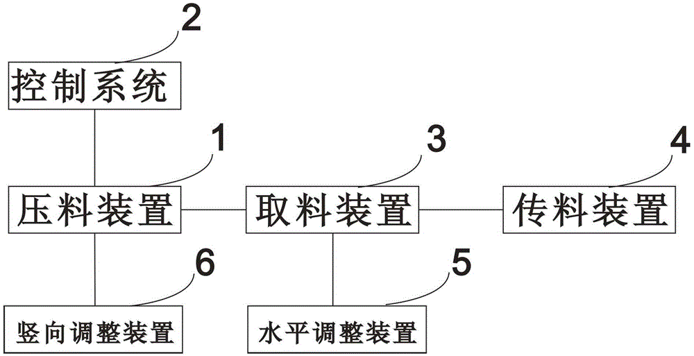
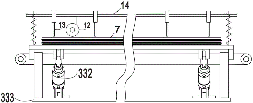
[0023] see figure 1 , figure 2 and image 3 , a bar conveyor, including a pressing device 1 for arranging the whole pile of multi-layer bars 7 into a single layer arrangement, a control system 2 for automatically controlling the pressing device, and a A retrieving device 3 for automatic single-root retrieving in the material device, a material transfer device 4 for transferring material from the reclaiming device, and an adjustment device for adjusting the bar specification; the adjustment device includes a bar specification The horizontal adjustment device 5 and the vertical adjustment device 6, the horizontal adjustment device 5 is connected with the material taking device 3, and the vertical adjustment device 6 is connected with the pressing device 1.

[0024] The pressing device 1 includes a tray 11 for placing the whole pile of multi-layer bars, a monolithic bar 12 for arranging the whole pile of multi-layer bars 7 into a single-layer arrangement, and a single-layer ar...

Embodiment 2

[0037] The difference from Embodiment 1 is that the reclaiming power device includes a power screw (not shown) connected to the reclaiming fork, and a second cylinder (not shown) for driving the power screw to move up and down Or a motor (not shown), so that the second cylinder or the motor drives the power screw to drive the up and down movement of the reclaiming fork.

Embodiment 3

[0039] see Figure 5 , different from Embodiment 1, the level adjustment device includes a horizontal slide plate 51, a horizontal screw rod 52 fixedly connected with the horizontal slide plate, a graduated handwheel 53 connected with the horizontal screw rod, which can be achieved through low-cost Scaled handwheel for quick and accurate adjustment of individual extractions for bar sizes.


PUM

PropertyMeasurementUnit
Inclinationaaaaaaaaaa

Abstract

The invention provides a bar conveyor, which comprises a bar pressing device, a control system, a bar taking device, a bar transferring device and an adjusting device, wherein the bar pressing device is used for arranging batches of multilayer bars into a single layer; the control system is used for controlling the bar pressing device automatically; the bar taking device is used for taking a single piece of bar automatically from the bar pressing device; the bar transferring device is used for transferring bars from the bar taking device; the adjusting device is used for adjusting the bar specifications and comprises a horizontal adjusting device and a vertical adjusting device for the bar specifications; the horizontal adjusting device is connected with the bar taking device; and the vertical adjusting device is connected with the bar pressing device. According to the bar conveyor, manual bar taking and storage are replaced, the labor intensity of workers is reduced greatly, and the automation degree and the production efficiency are improved greatly. During the production process, bars having different specifications are adjusted through the adjusting device, thereby solving the problems that an existing bar conveyor cannot convey extremely slender bars, sizes of bars for production cannot be adjusted freely, and the like.

Description


Claims


Application Information

Patent Timeline
Owner XIAMEN LANGUAN AUTOMATION TECH
Learn More