
Steering wheel lock

A steering wheel lock, automobile technology, applied in vehicle parts, anti-theft vehicle accessories, transportation and packaging, etc., can solve problems such as the inability to achieve the anti-theft effect, the lock body being sawed off, and the loss of the anti-theft effect.

Inactive Publication Date: 2013-06-12
RERLLY IND
View PDF5 Cites 2 Cited by
  • Summary
  • Abstract
  • Description
  • Claims
  • Application Information

AI Technical Summary

Problems solved by technology

[0002] In addition to the anti-theft device of the car door, the anti-theft of a general car will be equipped with a car steering wheel lock on the steering wheel to prevent thieves from stealing the vehicle. The long rod of the lock body and the telescopic rod are provided with hooks opposite to each other, and the lock body and the hooks on the telescopic rod are reversely buckled on the steering wheel, so that the long rod of the lock body extends out of the steering wheel. The outwardly protruding part can limit the rotation angle of the steering wheel to achieve the anti-theft effect. However, after the existing steering wheel lock is locked, there is still a considerable distance between the long rod outer end of the lock body and the car seat and the windshield. In the large space, the thief only needs to move the seat back, and the steering wheel still has room to rotate, so it cannot really achieve the anti-theft effect, and the protruding lock body is easily sawed off by the thief with a tool (saw blade), and loses its originality. Anti-theft effect; for this reason, in view of the above-mentioned deficiency in the general automobile steering wheel lock, the inventor has devoted himself to research and improvement, and then can create the present invention for the first time.

Method used


Image

  • Steering wheel lock
  • Steering wheel lock
  • Steering wheel lock

Examples


Embodiment Construction

[0016] Relevant present invention is for reaching above-mentioned purpose of use and effect, the technical means that adopts, presents preferred feasible embodiment hereby, and cooperates as shown in the accompanying drawings, detailed description is as follows:

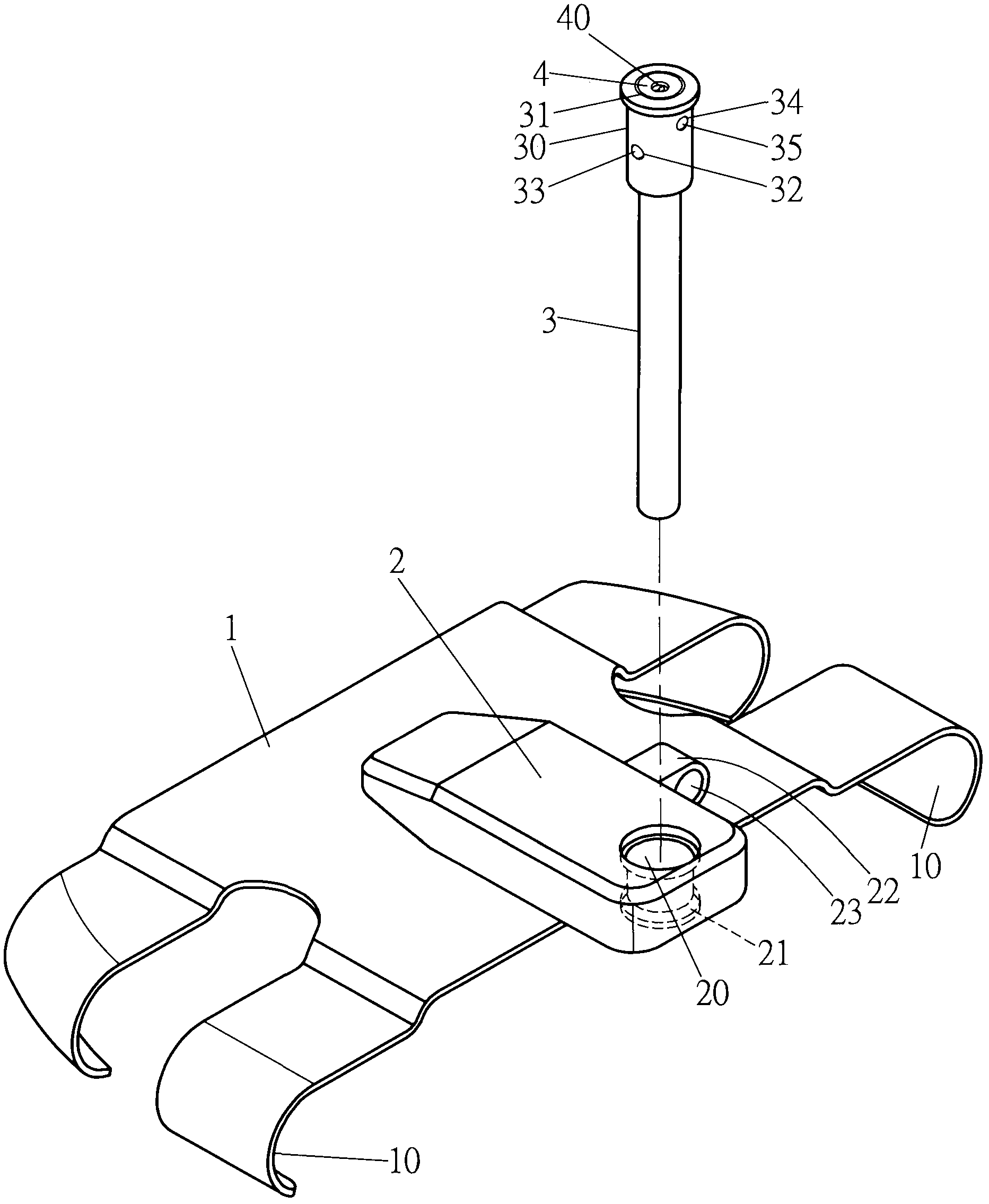
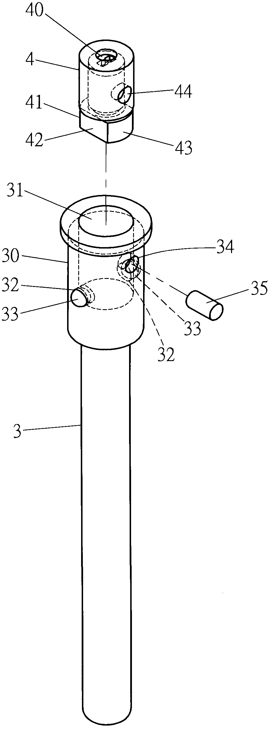
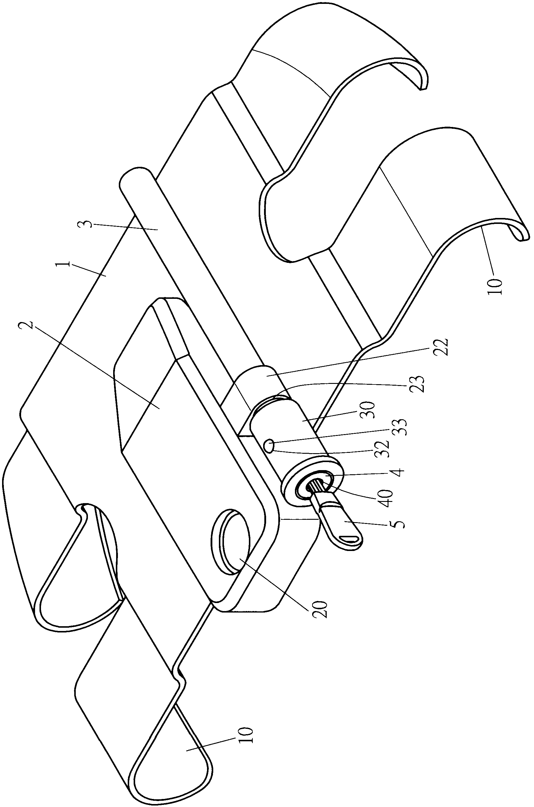
[0017] For an example of the invention, see figure 1 , figure 2 As shown, a main body 1 is mainly provided, and the two sides of the main body 1 are curved downward to be provided with buckling parts 10. The main body 1 is provided with a lock seat 2, and the lock seat 2 is provided with a lock rod socket 20. The bottom of the locking rod insertion hole 20 is provided with a slot 21, and one side of the lock base 2 is provided with a protrusion 22, and the protrusion 22 is provided with a positioning through hole 23; a locking rod 3 is located on the lock base 2 One end of the lock rod 3 is provided with a lock core seat 30, the lock core seat 30 is provided with a chamber 31, and the wall surface of the lock core ...


PUM


Abstract

The invention provides a steering wheel lock, which is mainly provided with a body, wherein two sides of the body are provided with fastening parts; the body is provided with a lock bracket; the lock bracket is provided with a lock bar inserting hole; one side of the lock bracket is provided with a protruding seat; a positioning through hole is formed in the protruding seat; and a lock bar is arranged on the lock bracket. Therefore, the body covers and is positioned on a steering wheel, and is pressed against and positioned on a fixed seat of the steering wheel, so that the steering wheel cannot rotate to realize an anti-theft function.

Description

technical field [0001] The invention relates to an automobile steering wheel lock, in particular to a lock that can be covered and positioned on the steering wheel so that the steering wheel cannot be rotated and can indeed achieve the effect of anti-theft. Background technique [0002] In addition to the anti-theft device of the car door, the anti-theft of a general car will be equipped with a car steering wheel lock on the steering wheel to prevent thieves from stealing the vehicle. The long rod of the lock body and the telescopic rod are provided with hooks opposite to each other, and the lock body and the hooks on the telescopic rod are reversely buckled on the steering wheel, so that the long rod of the lock body extends out of the steering wheel. The outwardly protruding part can limit the rotation angle of the steering wheel to achieve the anti-theft effect. However, after the existing steering wheel lock is locked, there is still a considerable distance between the l...

Claims


Application Information

Patent Timeline
IPC IPC(8): B60R25/022
Inventor 林郁宾
Owner RERLLY IND
Learn More