
Cantilever tail end vibration analysis and error compensation method

An error compensation and cantilever technology, applied in the field of mechanical vibration and robot technology, can solve the problems of low error compensation efficiency, poor low-frequency vibration suppression effect, lack of flexibility, etc., to improve accuracy and efficiency, and improve static and dynamic positioning The effect of precision

Inactive Publication Date: 2013-06-12
天津中科智能技术研究院有限公司
View PDF7 Cites 15 Cited by
  • Summary
  • Abstract
  • Description
  • Claims
  • Application Information

AI Technical Summary

Problems solved by technology

However, this vibration suppression method is inflexible, and the effect of low-frequency vibration suppression is not good; the error compensation method is to use the active actuator to compensate the position error caused by deformation or vibration, so as to improve the positioning accuracy of the end
Harbin Institute of Technology patent 200410013627.7 relates to a method for precise positioning of a six-degree-of-freedom parallel robot, which can effectively compensate for position errors caused by low-frequency vibrations, but has low compensation efficiency and poor accuracy for errors caused by high-frequency vibrations

Method used


Image

  • Cantilever tail end vibration analysis and error compensation method
  • Cantilever tail end vibration analysis and error compensation method
  • Cantilever tail end vibration analysis and error compensation method

Examples


Embodiment Construction

[0024] In order to make the objectives, technical solutions, and advantages of the present invention clearer, the following further describes the present invention in detail in conjunction with specific embodiments and with reference to the accompanying drawings.

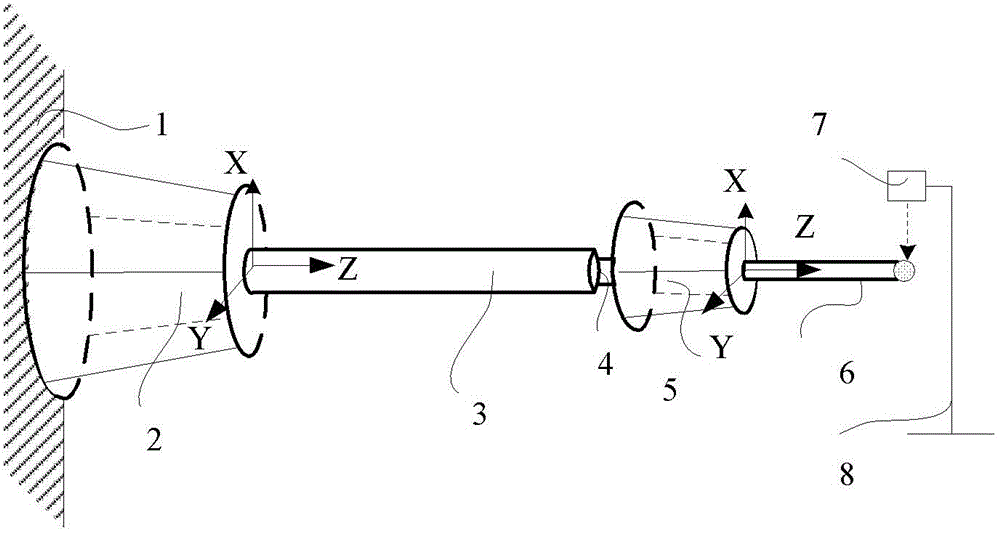
[0025] figure 1 It is a schematic diagram of the composition structure of the cantilever vibration analysis and error compensation method. The overall structure includes the base Stewart platform 2, the cantilever reduced by a certain proportion, the force sensor 4, the positioning Stewart platform 5, the actuator 6 and the laser displacement sensor 7. Among them, the Stewart platform consists of a motor, a motion platform, a fixed platform and six parallel, independently telescopic connecting rods. The change of the length of the telescopic rod is controlled by the motor to complete the position and posture transformation of the moving platform; the actuator is any type of actuator in the prior art. The fixed platform...


PUM


Abstract

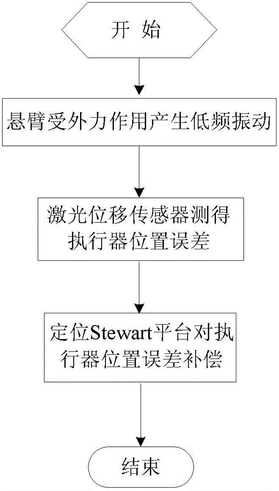
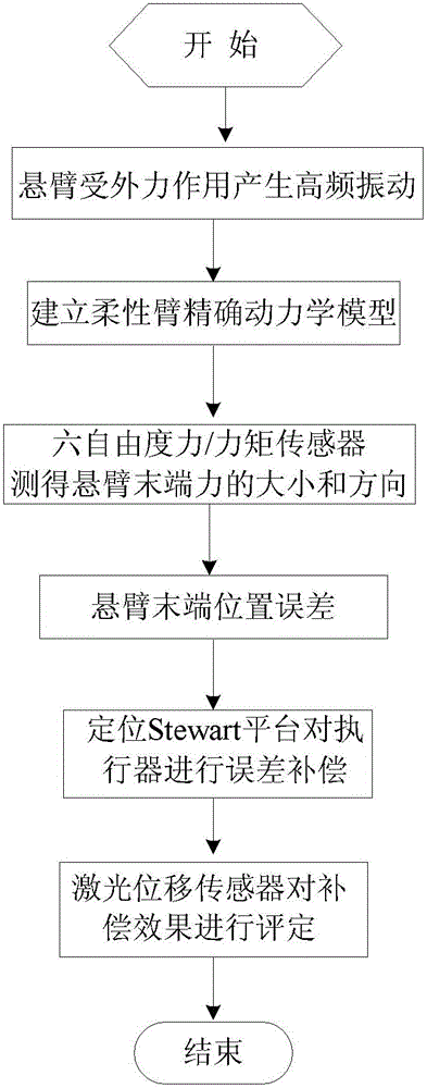
The invention discloses a cantilever tail end vibration analysis and error compensation method, which comprises the following steps: simulating low-frequency vibration of the cantilever by a base body Stewart platform, and compensating the space error of an actuator tail end by a positioning Stewart platform based on the value measured by a laser displacement transducer; and simulating high-frequency vibration of the cantilever by a scaled-down cantilever based on the parameterized standard excitation, measuring the space error of the actuator tail end based on a cantilever distribution parameter dynamic model and a force sensor, and compensating the space error by the positioning Stewart platform based on the measuring, wherein the compensation effect is assessed by the laser displacement transducer. According to the invention, the space error of the cantilever tail end is measured based on a cantilever precise dynamic model and the force sensor, which improves the error compensation precision and efficiency of the positioning Stewart platform; and meanwhile, based on the space error caused by the positioning Stewart platform in compensating high / low-frequency vibration, the static and dynamic positioning accuracy of the actuator can be improved.

Description

Technical field [0001] The invention relates to the application field of mechanical vibration and robot technology, in particular to a cantilever vibration analysis and error compensation method. Background technique [0002] Because of its light weight and fast moving speed, flexible cantilever occupies a very important position in applications such as unmanned remote sensing operations, precision manufacturing, and national defense. However, due to the large deflection and low damping of the flexible cantilever, it is easy to be subjected to external forces during the movement to produce continuous vibration, which affects the accuracy and efficiency of terminal positioning and limits its further application. The length of the cantilever used in engineering practice is generally greater than 5m, which takes up a large space, which makes the construction of the experimental platform inconvenient, and the platform is expensive, which brings difficulties to the vibration analysis ...

Claims


Application Information

Patent Timeline
IPC IPC(8): B25J9/16
Inventor 刘衍王学伟吴保林徐德
Owner 天津中科智能技术研究院有限公司
Learn More