Multifunctional belt conveyor roller replacement device
A belt conveyor, multi-functional technology, applied in the field of multi-functional belt conveyor roller replacement device, can solve the problems of unsafe operation, high labor intensity, belt damage, etc., and achieve improved operation efficiency, good adaptability, and easy adjustment Effect
- Summary
- Abstract
- Description
- Claims
- Application Information
AI Technical Summary
Problems solved by technology
Method used
Image
Examples
Embodiment 1
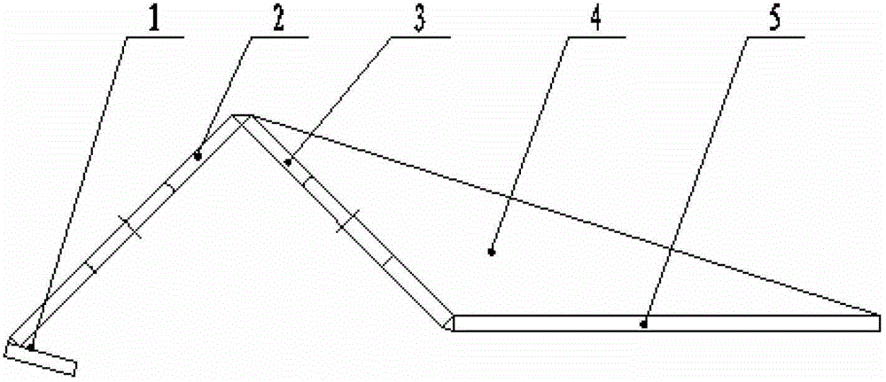
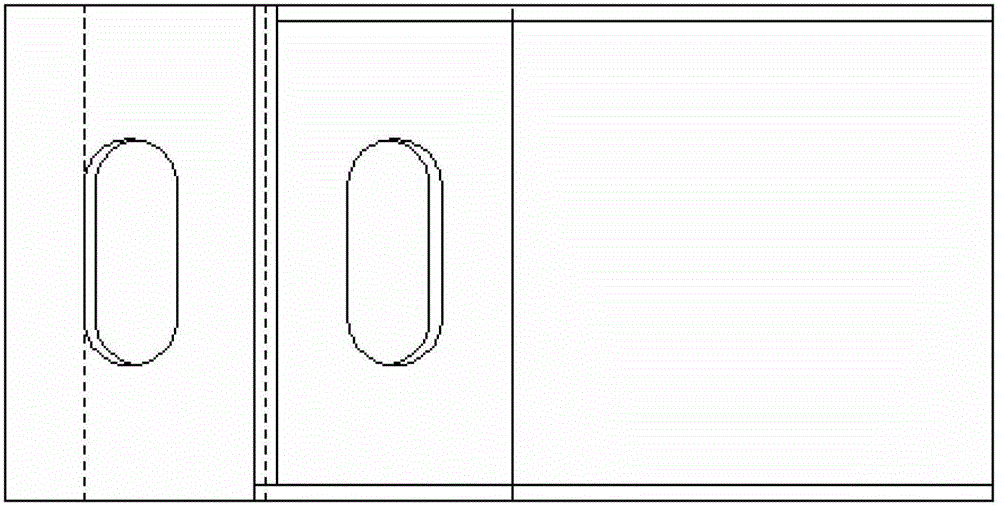
[0027] Such as figure 1 , figure 2 , Figure 7 , Figure 8 , Figure 9 , Figure 10 , Figure 11 As shown, a multifunctional belt conveyor idler roller replacement device includes a bracket device, a tooth tool and an underframe device. Pin hole 25, bracket seat 26, bracket handle 27, top seat 28 and limit wedge 29 are made up of, bracket seat 26 is concave structure, is respectively connected with a rotating shaft 24 at the left and right ends of bracket seat 26. The moment tube 23, the front portion of the rotating moment tube 23 is connected with the telescopic rod 21 by the nut 22, the telescopic rod 21 is a concave structure, and a bracket handle 27 is provided on the middle side of the bracket seat 26, and on the bracket seat 26 The other side is provided with a top seat 28, and a limit wedge 29 is respectively provided at both ends of the bracket seat 26, and three pin holes 25 are respectively arranged on both sides of the bracket handle 27 on the bracket seat 2...
Embodiment 2
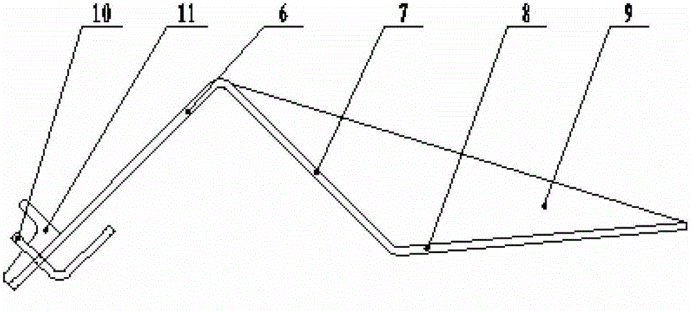
[0032] Such as image 3 , Figure 4 , Figure 7 , Figure 8 , Figure 11 As shown, a multifunctional belt conveyor idler roller replacement device includes a bracket device, a tooth tool and a universal underframe device. , pin hole 25, bracket seat 26, bracket handle 27, top seat 28 and limit wedge 29, the bracket seat 26 is a concave structure, and the left and right ends of the bracket seat 26 are respectively connected by pin shafts 24. Rotate the torque tube 23, the front portion of the rotating torque tube 23 is connected with the telescopic rod 21 by the nut 22, the telescopic rod 21 is a concave structure, a bracket handle 27 is provided on the middle side of the bracket seat 26, and the bracket handle 27 is arranged on the bracket seat 26 The other side of the top seat 28 is provided with a stop wedge 29 at both ends of the bracket seat 26, and three pin holes 25 are respectively established on both sides of the bracket handle 27 on the bracket seat 26. ;
[003...
Embodiment 3
[0037] Such as Figure 5 , Image 6 , Figure 7 , Figure 8 , Figure 11As shown, a multifunctional belt conveyor idler roller replacement device includes a bracket device, a tooth tool and a universal underframe device. , pin hole 25, bracket seat 26, bracket handle 27, top seat 28 and limit wedge 29, the bracket seat 26 is a concave structure, and the left and right ends of the bracket seat 26 are respectively connected by pin shafts 24. Rotate the torque tube 23, the front portion of the rotating torque tube 23 is connected with the telescopic rod 21 by the nut 22, the telescopic rod 21 is a concave structure, a bracket handle 27 is provided on the middle side of the bracket seat 26, and the bracket handle 27 is arranged on the bracket seat 26 The other side of the top seat 28 is provided with a stop wedge 29 at both ends of the bracket seat 26, and three pin holes 25 are respectively established on both sides of the bracket handle 27 on the bracket seat 26. ;
[0038...
PUM
 Abstract
Description
Claims
Application Information
 - R&D
- Intellectual Property
- Life Sciences
- Materials
- Tech Scout
- Unparalleled Data Quality
- Higher Quality Content
- 60% Fewer Hallucinations
Browse by: Latest US Patents, China's latest patents, Technical Efficacy Thesaurus, Application Domain, Technology Topic, Popular Technical Reports.
© 2025 PatSnap. All rights reserved.Legal|Privacy policy|Modern Slavery Act Transparency Statement|Sitemap|About US| Contact US: help@patsnap.com


