
Method for sending channel state information reference signal, base station and relays

A channel state information and reference signal technology, applied in the transmission of channel state information reference signals, base stations and relay fields, can solve the problems of the accuracy of system channel measurement and the low overall throughput performance of the system

Active Publication Date: 2013-06-05
CHINA MOBILE COMM GRP CO LTD
View PDF2 Cites 18 Cited by
  • Summary
  • Abstract
  • Description
  • Claims
  • Application Information

AI Technical Summary

Problems solved by technology

[0006] Embodiments of the present invention provide a channel state information reference signal transmission method, a base station, and a relay, to solve the problems of accuracy of system channel measurement and low overall system throughput performance caused by CSI-RS interference in the prior art question

Method used


Image

  • Method for sending channel state information reference signal, base station and relays
  • Method for sending channel state information reference signal, base station and relays
  • Method for sending channel state information reference signal, base station and relays

Examples


Embodiment 1

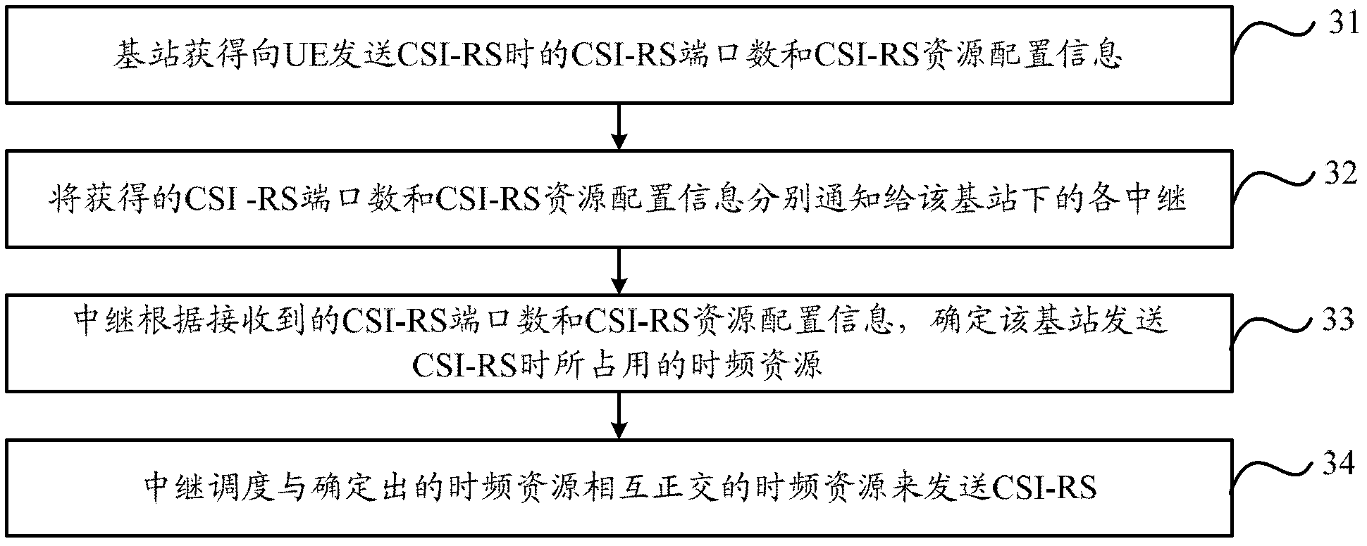
[0028] Such as image 3 As shown, it is a flow chart of the CSI-RS sending method in Embodiment 1 of the present invention, and its specific processing process is as follows:

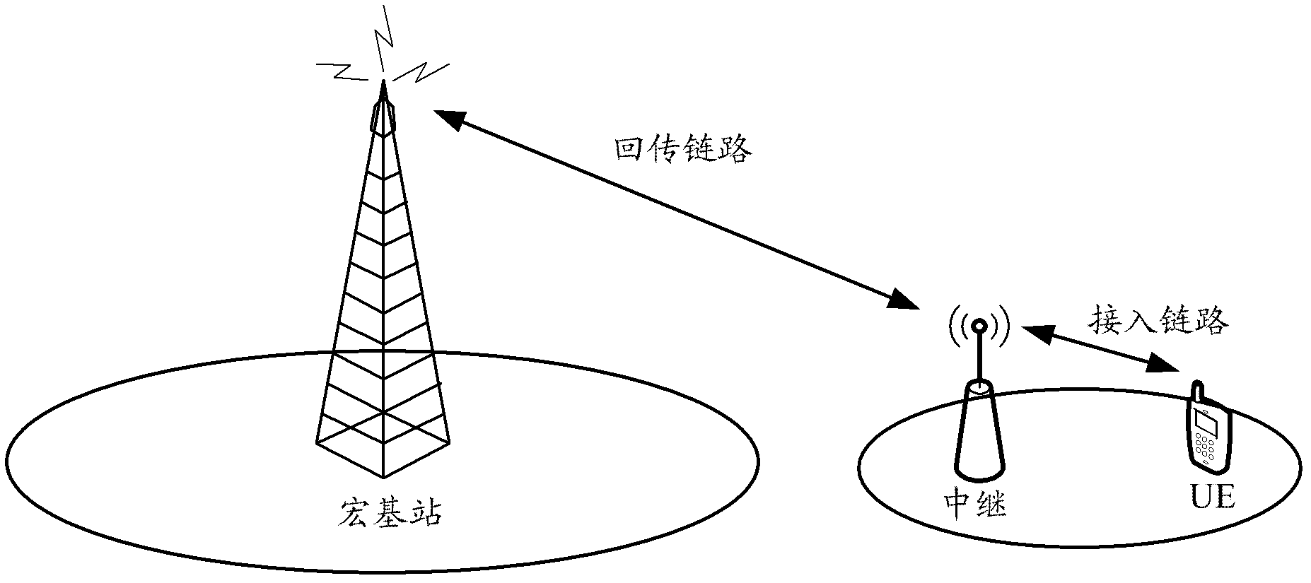
[0029] In step 31, the base station obtains the number of CSI-RS ports and CSI-RS resource configuration information when sending the CSI-RS to the UE.

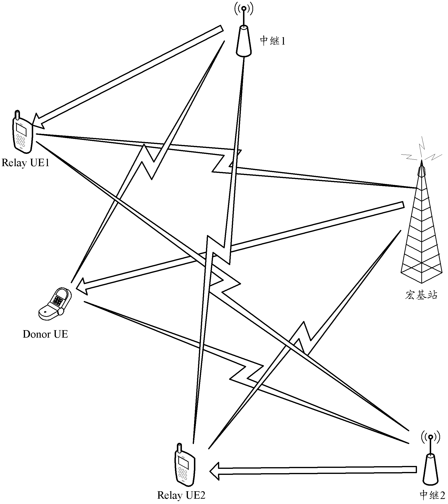
[0030] The base station is the above-mentioned macro base station, and the UE directly connected to the base station is a Donor UE, and the base station may be called a donor base station of the Donor UE.

[0031] When the macro base station sends CSI-RS to the Donor UE, it will allocate the number of CSI-RS ports and CSI-RS resource configuration information (such as 7bit indication information) for the Donor UE, where the macro base station can allocate all Donor UEs connected to the macro base station The same number of CSI-RS ports and the allocation of the same CSI-RS resource configuration information. The number of CSI-RS ports and CSI-RS reso...

Embodiment 2

[0056] Such as Figure 6 As shown, it is a flow chart of the CSI-RS sending method in Embodiment 2 of the present invention, and its specific processing process is as follows:

[0057] Step 61 , the relay reports the number of CSI-RS ports when sending the CSI-RS to the base station to which it belongs.

[0058] The base station is the above-mentioned macro base station, and the UE directly connected to the base station is a Donor UE, and the base station may be called a donor base station of the Donor UE.

[0059] In step 62, the base station allocates mutually orthogonal time-frequency resources for each UE connected to itself and each relay belonging to the base station according to the received numbers of CSI-RS ports.

[0060] Step 63: For each relay belonging to the base station, the base station notifies the relay of the time-frequency resource allocated to the relay, and the time-frequency resource is used for the relay to schedule the time-frequency resource to send ...


PUM


Abstract

The invention discloses a method for sending a channel state information reference signal, a base station and relays. The method includes that the base station obtains the number of channel state information reference signal (CSI-RS) ports and CSI-RS resource configuration information during sending of a CRS-RS to a terminal; the obtained number of the CSI-RS ports and the CSI-RS resource configuration information are notified to the relays under the base station, the number of the CSI-RS ports and the CSI-RS resource configuration information are used by the relays to schedule time-frequency resource orthogonal with time-frequency resource occupied when the base station sends the CSI-RS so as to send the CSI-RS. By means of the technical scheme, the problem in the prior art that system channel measuring accuracy and the whole system throughput performance are low due to CSI-RS disturbance is solved.

Description

technical field [0001] The present invention relates to the technical field of mobile communication, in particular to a method for sending a channel state information reference signal, a base station and a relay. Background technique [0002] The Time-Division Long-Term Evolution (TD-LTE, Time-Division Long-Term Evolution) system provides a higher transmission rate and better user experience than the second-generation mobile communication system and the third-generation mobile communication system. The early deployment of the TD-LTE system was aimed at hotspot areas, but with the continuous increase in the number of data service users, users hope to enjoy the high-speed experience brought by the TD-LTE system in a wider range, which requires TD - The LTE system can provide services for users in various scenarios, including dense cities with complex propagation environments, remote suburbs, indoor and high-speed coverage, etc. [0003] In order to cope with various complex w...

Claims


Application Information

Patent Timeline
Patent Type & Authority Applications(China)
IPC IPC(8): H04L1/00H04W72/08H04W72/12H04W72/54
Inventor 刘建军闫渊杨宁沈晓冬韩璐刘光毅
Owner CHINA MOBILE COMM GRP CO LTD
Learn More