
A reducer test device and a reducer production line

A test device and reducer technology, applied in the field of reducers, to achieve the effects of improving detection accuracy, improving factory inspection level, and optimizing performance, high efficiency and reliability

Active Publication Date: 2015-09-02
SUOTE TRANSMISSION EQUIP
View PDF8 Cites 1 Cited by
  • Summary
  • Abstract
  • Description
  • Claims
  • Application Information

AI Technical Summary

Problems solved by technology

[0004] In view of this, the present invention proposes a speed reducer test device and a speed reducer production line to solve the problem of the no-load run-in test of the speed reducer leaving the factory

Method used


Image

  • A reducer test device and a reducer production line
  • A reducer test device and a reducer production line
  • A reducer test device and a reducer production line

Examples


Embodiment Construction

[0020] It should be noted that, in the case of no conflict, the embodiments of the present invention and the features in the embodiments can be combined with each other. The present invention will be described in detail below with reference to the accompanying drawings and examples.

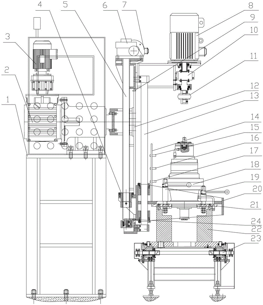
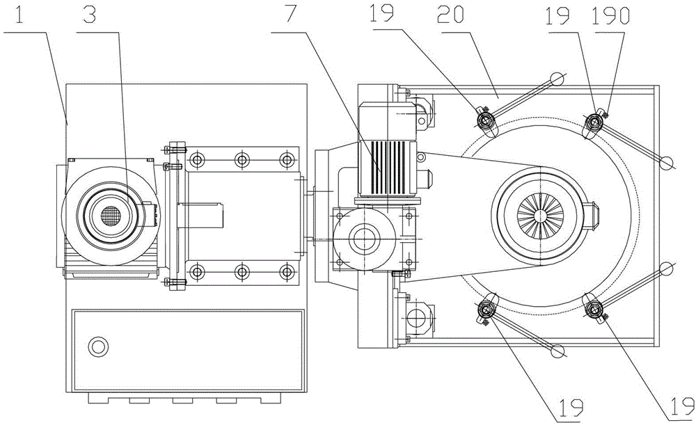
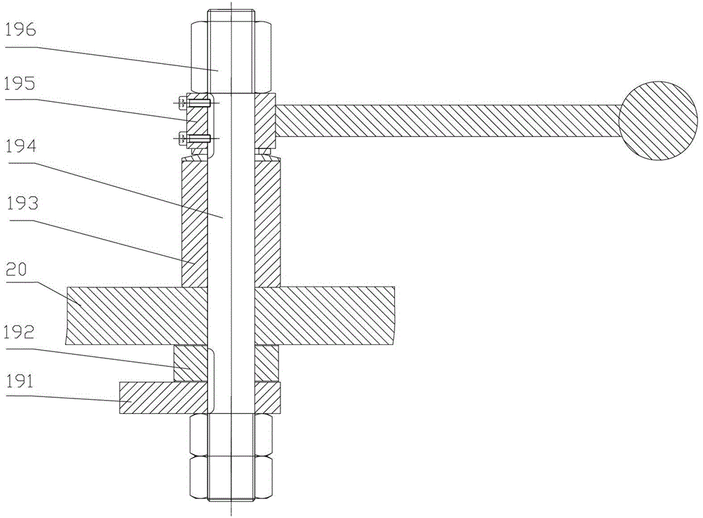
[0021] Such as Figure 1 to Figure 3 As shown, a reducer test production line of the present invention includes a reducer test device, a reducer conveyor belt 23, a reducer conveying seat 22, the reducer conveying seat 22 is placed on the reducer conveyor belt 23, and the reducer test device is placed At the reducer test station. The reducer conveyor belt 23 and the reducer conveying seat 22 are used to transport the reducer, and the test station issues the order to be tested, and the reducer conveyor belt 23 can automatically locate and transport the reducer according to the required sequence, without additional logistics conveying equipment and personnel.

[0022] The reducer test device is ...


PUM


Abstract

The invention discloses a speed reducer test device which comprises a base, a turnover mechanism, a lifting mechanism, a drive mechanism and a speed reducer installation platform. The turnover mechanism is installed on the base and is used for driving the lifting mechanism, the drive mechanism and the speed reducer installation platform to rotate. The speed reducer installation platform is used for installing the to-be-tested speed reducer. The speed reducer installation platform is connected with the lifting mechanism. The lifting mechanism is used for driving the speed reducer installation platform to lift up and down. The drive mechanism is used for driving the to-be-tested speed reducer to rotate. The invention further discloses a speed reducer production line. The speed reducer test device can simulate the speed reducer to conduct a leaving-factory no-load running-in test in an installing state of engineer machinery equipment and is high in production line automation, high in test efficiency and suitable for various speed reducers.

Description

technical field [0001] The invention relates to the field of reducers, in particular to a reducer test device and a reducer production line. Background technique [0002] At present, the slewing reducer, traveling reducer and hoisting reducer widely used in construction machinery equipment are extremely important components. The working performance, reliability and service life of the reducer will directly have an important impact on the main engine. Although strict inspections have been carried out during the processing of the parts, and the assembly process is carried out according to the assembly process, in order to ensure that each manufactured product is a qualified product, it is necessary to carry out a certain period of no-load running-in. [0003] At present, the test methods for domestic reducer manufacturers to carry out factory no-load running-in are relatively simple, with low degree of equipment automation, poor compatibility, and separation from the reducer a...

Claims


Application Information

Patent Timeline
Patent Type & Authority Patents(China)
IPC IPC(8): G01M13/02
Inventor 邢子平谢彦
Owner SUOTE TRANSMISSION EQUIP
Learn More