Non-contact sealing system

A non-contact, sealing liquid technology, which is applied in the direction of engine sealing, mining fluid, wellbore/well parts, etc., can solve the problems of large sealing resistance, difficulty, fluid backflow, etc., and achieve reduced working energy consumption and long service life , a wide range of effects

Inactive Publication Date: 2014-03-12
SUZHOU DAYI EQUIP TECH
View PDF4 Cites 0 Cited by
  • Summary
  • Abstract
  • Description
  • Claims
  • Application Information

AI Technical Summary

Problems solved by technology

In addition, the steel wire rope in the oil suction pipe needs to perform reciprocating motion with a large stroke, especially considering that the cross section of the steel wire rope is not an ideal smooth circular cross section, and its long-term reliable sealing problem has not been effectively solved
The study found that the shortcomings of the contact sealing method are: first, the sealing method may cause high sealing resistance and high energy consumption of the oil pumping system due to the tight fit; or it is difficult to handle the high pressure ( Such as 0.5MPa) of natural gas to form an effective seal; second, this sealing method has the problem that the seal is easy to wear, which leads to seal failure, especially when the reciprocating stroke of the moving part is large and the cross-sectional shape changes with time, the traditional contact seal In this way, the wear problem of the seal is particularly prominent, and it causes the problem of long-term reliable sealing; third, a factor that needs to be considered in the application of this type of sealing system is that there is a large uncertainty in the pressure of the high-pressure fluid in the pipeline characteristics, which makes it difficult to perform non-contact sealing with fluid
For example, for pumping units, if the pressure of the fluid that realizes the sealing function cannot change rapidly with the pressure of the sealed natural gas, the seal may fail due to insufficient pressure of the sealing fluid, or the fluid may flow back to the natural gas due to excessive pressure go in the cavity

Method used


Image

  • Non-contact sealing system
  • Non-contact sealing system
  • Non-contact sealing system

Examples


Embodiment Construction

[0037] In order to make the object, technical solution and advantages of the present invention clearer, the present invention will be further described in detail below in conjunction with the accompanying drawings and embodiments. It should be understood that the specific embodiments described here are only used to explain the present invention, not to limit the present invention.

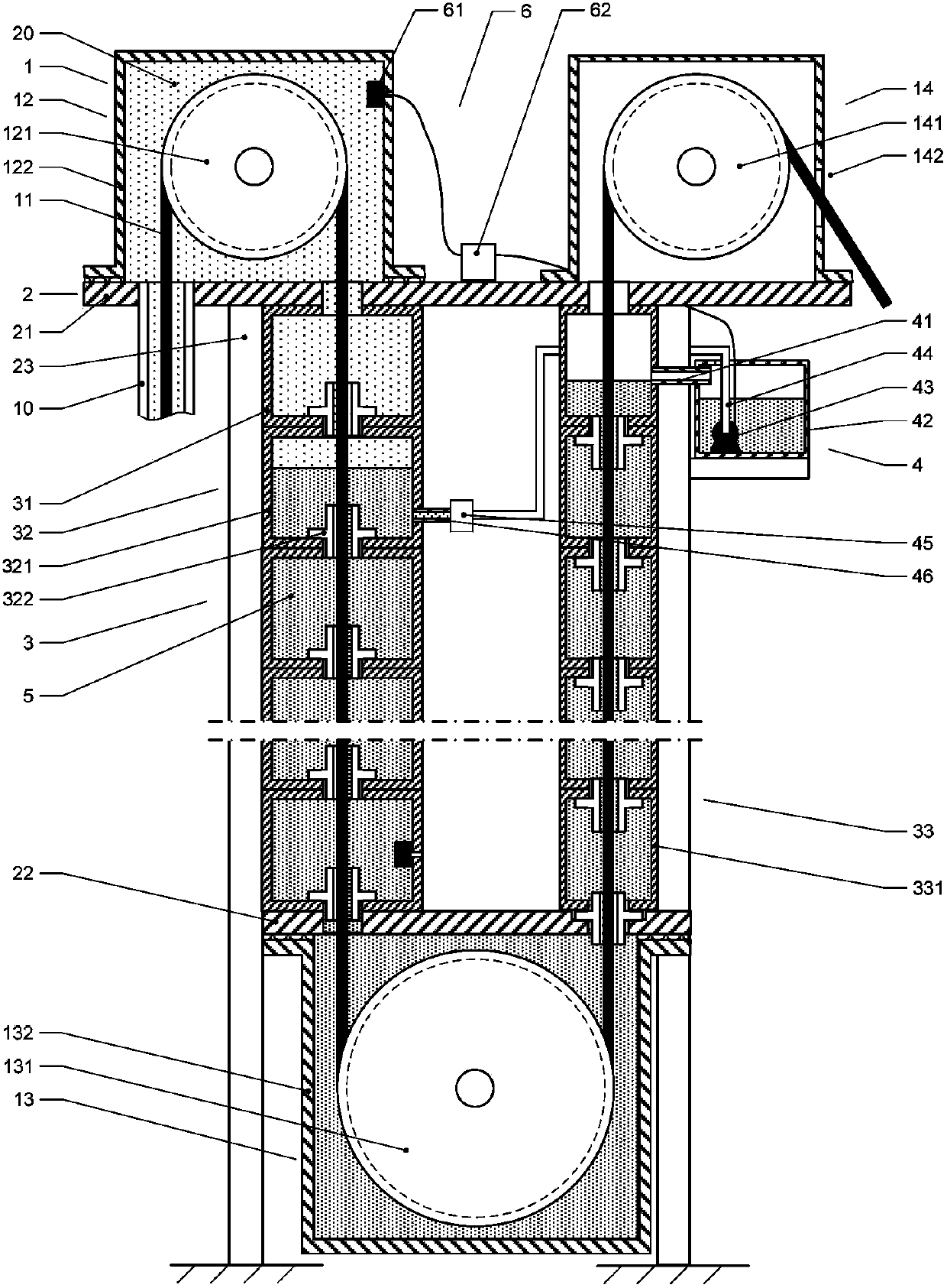
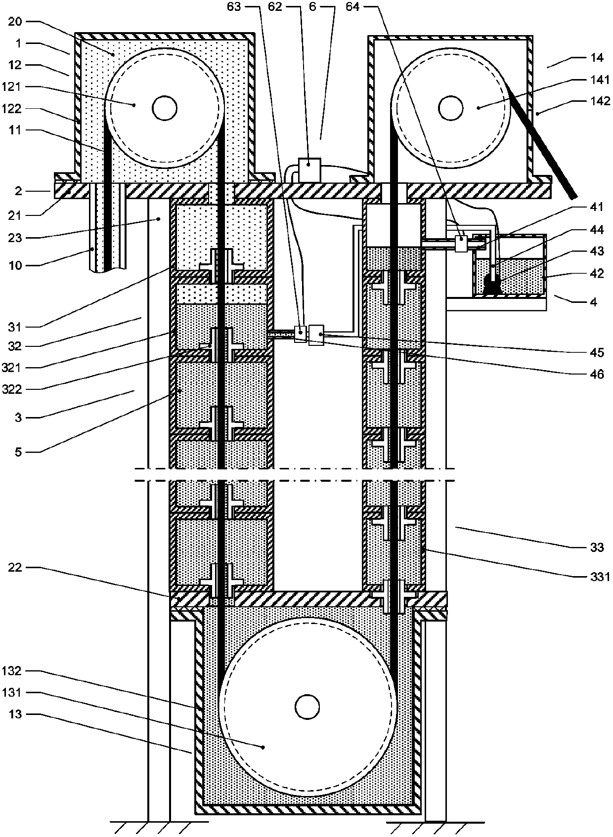
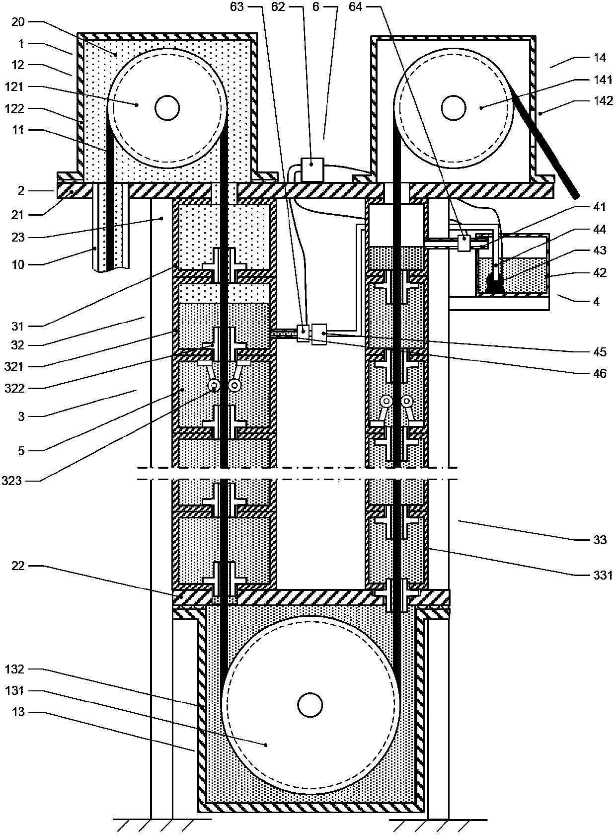
[0038] As mentioned above, there is often a type of sealing requirement for moving parts in the industry. It needs to perform effective sealing between the cavity containing high-pressure fluid and the moving parts in the cavity to prevent high-pressure fluid from passing through the cavity and moving parts. The gap between them flows out of the cavity. However, there are various deficiencies in the sealing methods for such moving parts in the prior art, so in the present invention, it is desired to construct a new non-contact sealing system and its sealing method in order to achieve a better seali...


PUM


Abstract

The invention discloses a system for actuating non-contact sealing to moving parts. The system comprises a pulley group, a support frame, sealing pipeline units and a liquid supply assembly. The pulley group is used for delivering the moving parts serving as sealing objects along an upstream journey and a downstream journey, the sealing pipeline units are respectively arranged along the upstream journey and the downstream journey of the moving parts and are respectively formed by connecting multiple sections of pipes in series, and adjacent pipe sections are connected with transition pipes with small pipe diameter. The liquid supply assembly is used for delivering sealing liquid to downstream sealing pipeline units and simultaneously is communicated with the upstream sealing pipeline units to keep backflow of the sealing liquid. The invention further discloses other optimized structural patterns. The non-contact sealing system has the advantages of being free of abrasion, small in sealing resistance and reliable in long-term operation, can enable sealing pressure to be adjusted along with fluid pressure fluctuation in adaptive mode, and is especially suitable for effective sealing of the moving parts, such as oil pumping unit steel wire ropes.

Description

technical field [0001] The invention belongs to the field of sealing technology, and more specifically relates to a non-contact sealing system that can be used between a cavity containing high-pressure fluid and a moving part in the cavity, and is especially suitable for oil pumping units and the like Non-contact sealing applications for equipment. Background technique [0002] There is a kind of sealing requirement for moving parts in the industry. It needs to perform effective sealing between the cavity containing high-pressure fluid and the moving parts in the cavity, so as to prevent the high-pressure fluid from flowing through the gap between the cavity and the moving parts. out of the cavity. When the cross-sectional shape of the moving part has time-varying characteristics and the sealing resistance cannot be too large, the problem of long-term reliable sealing is particularly prominent. [0003] Take the pumping unit used in the oil extraction process as an example...

Claims


Application Information

Patent Timeline
Patent Type & Authority Patents(China)
IPC IPC(8): F16J15/40E21B43/00
Inventor 陈学东陈清海姜伟李小清严可涵
Owner SUZHOU DAYI EQUIP TECH
Why Eureka
Try Eureka