Positive-pressure pulse type flushing-pipe injector for detaining passages of blood vessels

A pulse type, syringe technology, applied in the field of medical equipment, can solve the problems such as difficult to achieve the ideal effect, and achieve the effect of simple structure, convenient use and low cost

Inactive Publication Date: 2014-09-03
陆培华 +2
View PDF6 Cites 0 Cited by
  • Summary
  • Abstract
  • Description
  • Claims
  • Application Information

AI Technical Summary

Problems solved by technology

In order to achieve a suitable pulse or wave flushing, operating nurses often need training, but because it is operated by hand, it is difficult to achieve the desired effect

Method used


Image

  • Positive-pressure pulse type flushing-pipe injector for detaining passages of blood vessels
  • Positive-pressure pulse type flushing-pipe injector for detaining passages of blood vessels
  • Positive-pressure pulse type flushing-pipe injector for detaining passages of blood vessels

Examples


Embodiment 1

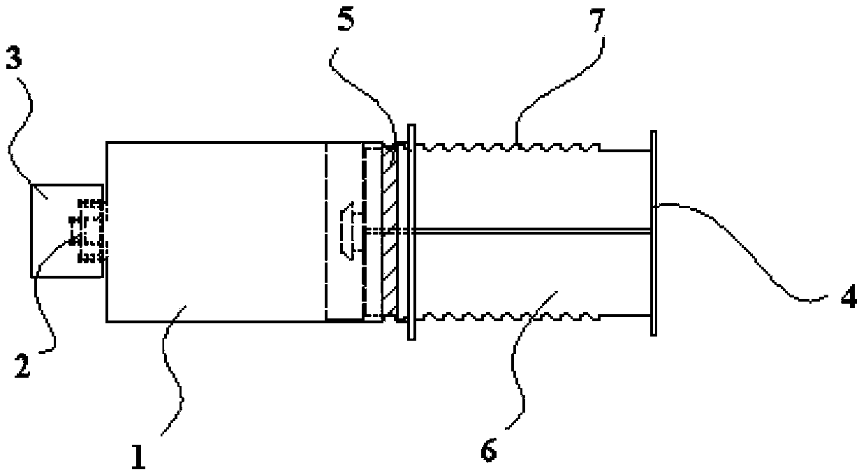
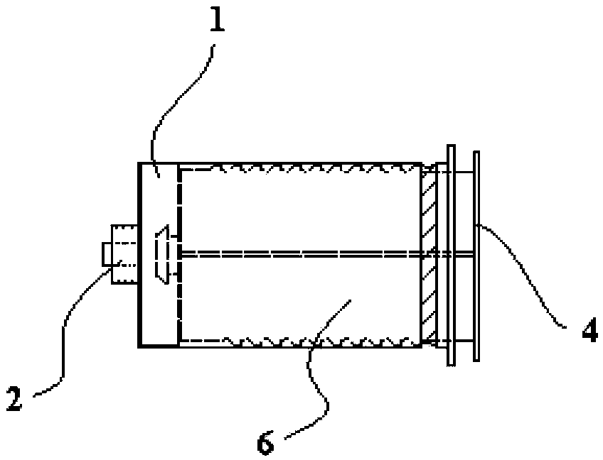
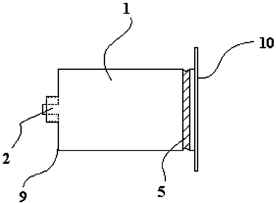
[0030] Such as figure 1 , figure 2 , image 3 , Figure 4 and Figure 5 Shown: In this embodiment, the injection syringe 1 has a cavity inside and a piston device inside the cavity. Specifically, the first blocking body is a blocking convex ring 5 protruding from the inner wall of the injection syringe 1, and the second blocking body is a corrugated tooth 7 arranged on the piston push rod 6, and the corrugated tooth 7 is pushed along the piston. The length of the rod 6 is distributed so that the tooth tips of the wave teeth 7 can contact with the blocking convex ring 5 . The distribution length of the corrugated teeth 7 on the piston push rod 6 is less than the length of the piston push rod 6, so as to form a smooth zone at the end of the piston push rod 6, that is, at the junction of the piston push rod 6 and the piston body 18. A section of smooth area, the smooth area will not contact with the blocking convex ring 5 in the injection syringe 1, when the piston body 18 ...

Embodiment 2

[0037] Such as Figure 6 , Figure 7 , Figure 8 , Figure 9 and Figure 10 As shown: in this embodiment, there are two cavities in the injection syringe 1, that is, the cavity in the injection syringe 1 includes a first cavity 15 and a second cavity 16, and the first cavity 15 and the second cavity The body 16 is isolated by the partition 12 in the injection syringe 1, and the first cavity 15 and the second cavity 16 are all connected with the injection outlet 2; the first cavity 15 is provided with a first piston device 13, and the second cavity The body 16 is provided with a second piston device 14; the length of the piston push rod 6 of the second piston device 14 is not shorter than the length of the piston push rod 6 of the first piston device 13. In the embodiment of the present invention, the length of the piston push rod 6 of the second piston device 14 is greater than the length of the piston push rod 6 of the first piston device 13 .

[0038] In this embodiment...


PUM


Abstract

The invention relates to a positive-pressure pulse type flushing-pipe injector for the detaining passages of blood vessels, which comprises an injection needle cylinder, wherein at least one hollow cavity is arranged in the injection needle cylinder; a piston device in matching connection is arranged in the hollow cavity of the injection needle cylinder, the piston device comprises a piston body and a piston push rod, and the piston body can be pushed by the piston push rod to move in the hollow cavity of the injection needle cylinder; a first obstruction body is arranged on the inner wall of the injection needle cylinder, and the first obstruction body is adjacent to the second end of the injection needle cylinder in the injection needle cylinder; a second obstruction body is arranged on the piston push rod of the piston device, and the second obstruction body and the first obstruction body are connected in a matching way; and when the piston body is pushed by the piston push rod to move in the hollow cavity of the injection needle cylinder, liquid in the hollow cavity of the injection needle cylinder can be ejected from an injection outlet in a pulse type. The positive-pressure pulse type flushing-pipe injector for the detaining passages of the blood vessels has a simple and compact structure and low cost, is convenient to use, can conveniently execute pulse type or wave type flushing and is safe and reliable.

Description

technical field [0001] The invention relates to a syringe, in particular to a positive pressure pulse type flushing syringe for blood vessel indwelling access, which belongs to the technical field of medical instruments. Background technique [0002] Vascular indwelling catheter is a medical device widely used in clinic. It is easy to operate, safe and convenient. It not only solves the pain of repeated puncture for patients, protects blood vessels, but also reduces the nursing workload of nurses. Patients without self-awareness who need multiple injections but are difficult to get needles, especially critically ill patients, can open the blood vessel channel at any time to improve the success rate of rescue. During the use of vascular indwelling technology, blood often flows back into the indwelling needle and coagulates to block the vascular channel when the catheter is locked. Now, heparin saline is required to lock the catheter after each vascular infusion to prevent coa...

Claims


Application Information

Patent Timeline
Patent Type & Authority Patents(China)
IPC IPC(8): A61M25/00A61M5/00
Inventor 陆培华高宏曹烽
Owner 陆培华
Why Eureka
Try Eureka