Method for display and navigation to clinical events

A technology for events and clinical information, applied in special data processing applications, healthcare resources or facilities, medical equipment, etc., to solve problems such as time-consuming

Inactive Publication Date: 2013-04-17
KONINKLIJKE PHILIPS ELECTRONICS NV
View PDF6 Cites 9 Cited by
  • Summary
  • Abstract
  • Description
  • Claims
  • Application Information

AI Technical Summary

Problems solved by technology

For an average heart rate of about 70 beats per minute, scanning

Method used


Image

  • Method for display and navigation to clinical events
  • Method for display and navigation to clinical events
  • Method for display and navigation to clinical events

Examples


Embodiment Construction

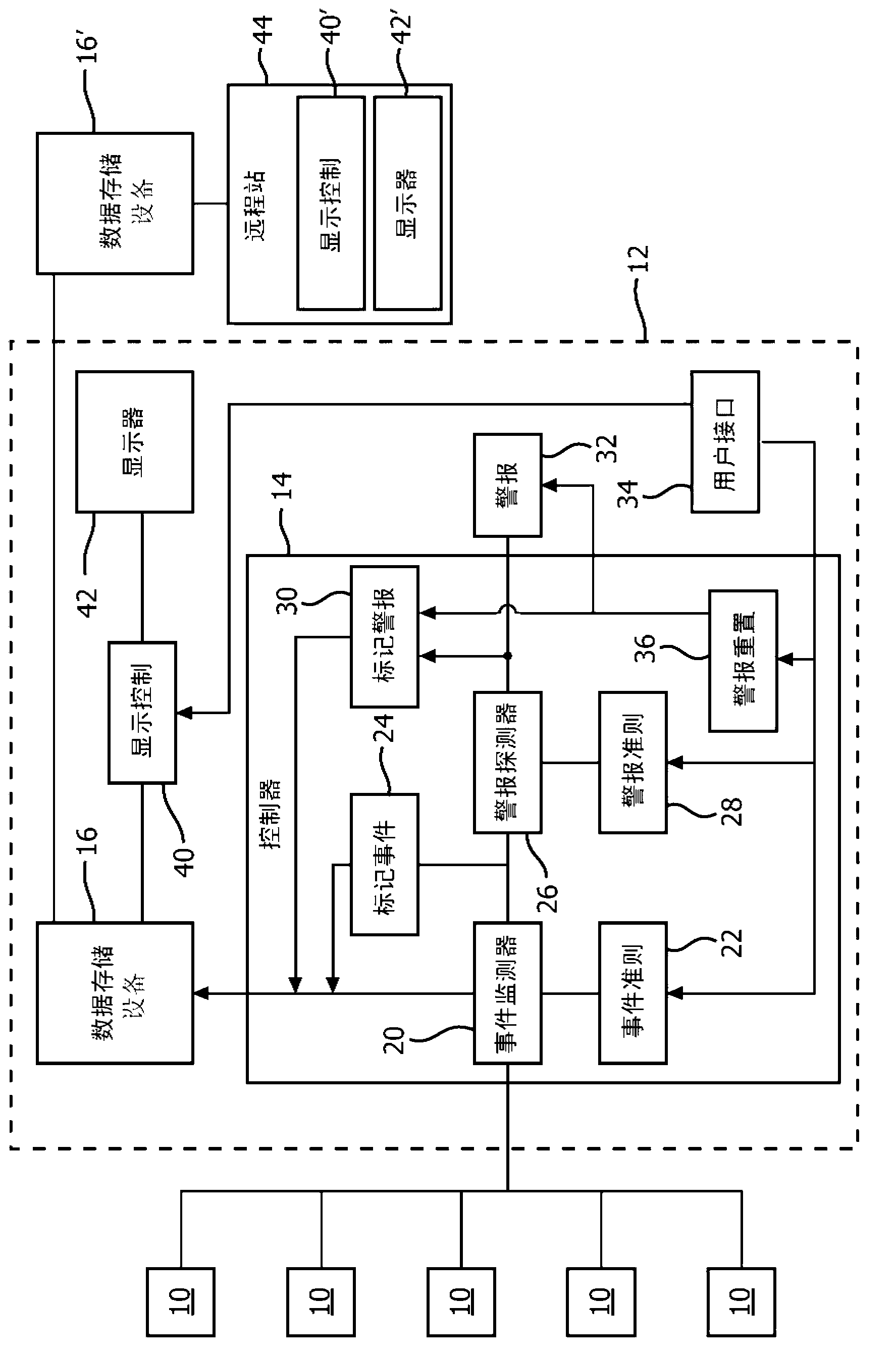
[0021] refer to figure 1 , using various medical monitoring devices or sensors that measure physiological parameters of the patient and generate physiological or clinical data indicative thereof, or the clinical information system 10 monitors the patient (not shown). These medical monitoring devices or clinical information 10 may include ECG sensors, IV fluid pumps, blood pressure sensors, SpO2 sensors, pulse sensors, thermometers, respiration sensors, gas sensors, therapy administration events and clinical indications or administration treatments, among others. Of course, other medical monitoring devices 10 may be associated with the patient, and not all of the aforementioned medical monitoring devices 10 need be associated with the patient at any given time. It should be understood that although five medical or clinical devices 10 are illustrated, fewer or more medical monitoring devices are contemplated. As used herein, medical monitoring device 10 represents a source of d...


PUM


Abstract

Visual renderings of medical events and alarms are generated by a display controller (114) and displayed on a display (42, 42'). The display controller is programmed to receive data indicative of physiological or clinical status versus time of a selected patient from a data store (16, 16') and detect events and/or alarms. An event object is created for each event/alarm segment, including a bar (72, 74) extending along a time line (88). Each event object is labeled using at least one of color coding, height coding, color intensity coding, and character coding.

Description

technical field [0001] The present application relates to medical monitoring and clinical data display devices for monitoring the physiological condition of patients. The present invention finds particular application in improving the display and navigation of events of interest containing patient information on patient monitoring devices, central monitoring stations, single-patient or multi-patient meter displays, and will be described with particular reference to these. Background technique [0002] Today, a limited amount of physiological data can be displayed on patient monitoring devices. When an alarm is triggered or an event is detected due to a measured change in a patient's physiological condition or a clinical event, data related to the alarm or event is displayed. To better diagnose the patient's current physiological condition, the clinician reviews data from multiple sensors leading up to and during the alarm or event. Monitors typically display current data a...

Claims


Application Information

Patent Timeline
IPC IPC(8): G06F19/00G16H10/60
CPCG16H40/63G16H10/60G16H40/20
Inventor B·D·格罗斯D·施瓦茨曼D·Y·金E·J·曾格
Owner KONINKLIJKE PHILIPS ELECTRONICS NV
Why Eureka
Try Eureka