Method for reducing particulate emissions on a direct-injection petrol engine

An engine, direct technology, applied in the direction of engine components, engine control, combustion engine, etc., can solve problems such as damage to energy supply, and achieve the effect of limiting energy consumption

Active Publication Date: 2013-04-03
VALEO SYST DE CONTROLE MOTEUR
View PDF10 Cites 1 Cited by
  • Summary
  • Abstract
  • Description
  • Claims
  • Application Information

AI Technical Summary

Problems solved by technology

However, such a strategy leads to a detrimental energy supply to the overall energy balance of the engine

Method used


Image

  • Method for reducing particulate emissions on a direct-injection petrol engine
  • Method for reducing particulate emissions on a direct-injection petrol engine

Examples


Embodiment Construction

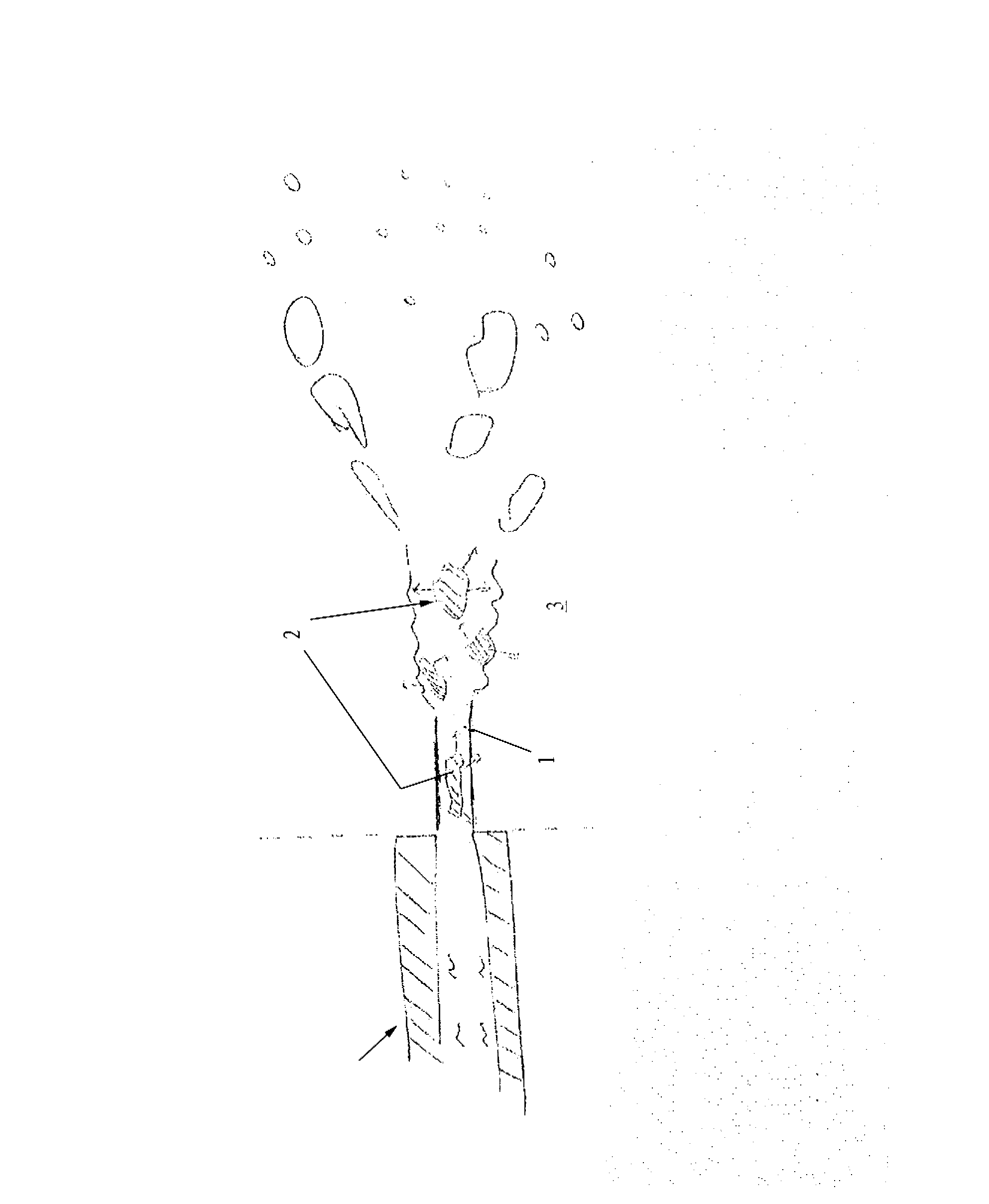
[0035] The invention relates firstly to a method for controlling an engine operating with direct injection of fuel, in particular gasoline, into the combustion chamber of the engine, with the aim of reducing the amount of particles emitted by the engine. In particular, it will relate to stratified-charge engines.

[0036] By particles is meant solid compounds formed during the combustion taking place in the combustion chamber. In other words, these are solid products of the chemical reactions that take place in the combustion chamber between the fuel and the oxidant, and originate in particular from fractions of liquid fuels subjected to high temperatures.

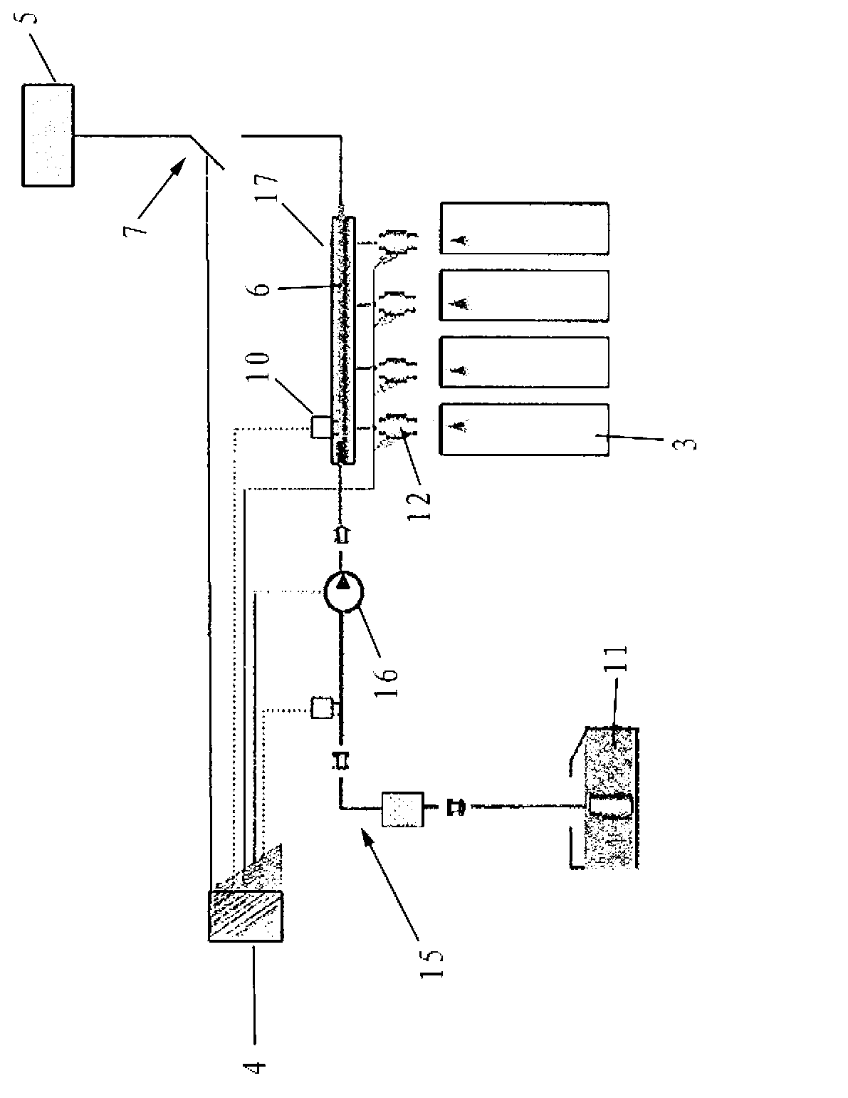
[0037] According to the invention, the operating phase of the engine, in particular the operating point and / or the phase-of-life point, is determined and, according to the found operating phase, the fuel is injected into the combustion chamber before it is introduced into the combustion chamber. heating.

[0038] In orde...


PUM


Abstract

The invention relates to a method and a device for controlling an engine operating with direct fuel injection, notably direct petrol injection, into a combustion chamber (3) of the engine. According to the invention: - an engine operating phase is determined, - the fuel is heated before it is introduced into the combustion chamber (3), according to said phase. The invention also relates to the combination of such a control device with an engine fuel supply circuit.

Description

technical field [0001] The invention relates to a method and a device for controlling an engine operating with direct injection of fuel, in particular gasoline, into a combustion chamber of the engine, and to an assembly having such a device and an engine fuel supply circuit. It will find application especially in the field of motor vehicles. Background technique [0002] Currently, in the field of diesel engines, it is known practice to employ particulate filters or FAPs to reduce particulate emissions and to meet currently enforced pollutant emission reduction standards. However, so far there are no regulations covering particulate emissions from gasoline engines. If such standards were enforced, especially with regard to maximum permissible amounts of particulate matter, compliance with them would prove particularly difficult, especially in the case of direct injection engines. [0003] This is because particulate emissions are mainly dependent on the presence of liquid...

Claims


Application Information

Patent Timeline
IPC IPC(8): F02M31/125F02M53/06F02D41/04F02D41/38
CPCF02D41/047F02M53/02Y02T10/126F02D35/025F02M53/06F02D35/023F02D2200/0606F02D41/3818F02D2250/02F02D35/026F02M63/0225F02M31/125F02D35/024Y02T10/12
Inventor V.皮克隆D.福尼高尔特P-H.莱格兰德
Owner VALEO SYST DE CONTROLE MOTEUR
Why Eureka
Try Eureka