
Floating connection mechanism used between hard face plate and printed board

A floating connection, printed board technology, applied in the direction of connection, connecting device parts, electrical components, etc., can solve the problem of effective installation, the inability to install the connector, the inability to guarantee the connector, and the buckling of the printed board at the same time. , to solve the effect of poor contact or buckling of printed boards

Active Publication Date: 2013-04-03
SICHUAN HUAFENG ENTERPRISE GRP
View PDF5 Cites 9 Cited by
  • Summary
  • Abstract
  • Description
  • Claims
  • Application Information

AI Technical Summary

Problems solved by technology

[0005] The technical problem to be solved by the present invention is to provide a floating connection mechanism between the hard panel and the printed board, which can connect the connector between the hard panel and the printed board. The installation errors on both sides are compensated in the axial and radial directions, which solves the phenomenon of poor contact of conductive contacts or buckling of printed boards; and solves the problem that the installation of multiple connectors between the hard panel and the printed board cannot be guaranteed at the same time The problem that each connector is installed effectively and the installation position of the connector cannot be adjusted

Method used


Image

  • Floating connection mechanism used between hard face plate and printed board
  • Floating connection mechanism used between hard face plate and printed board

Examples


Embodiment Construction

[0017] Specific embodiments of the present invention will be described in detail below in conjunction with the accompanying drawings.

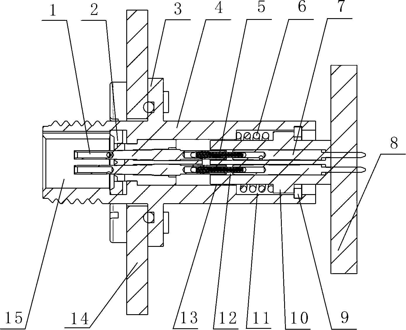
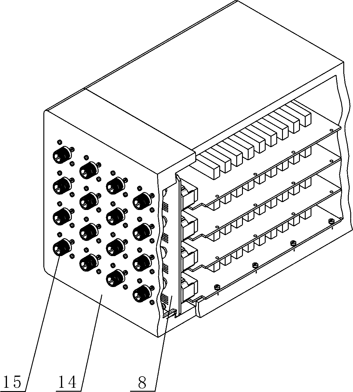
[0018] like figure 1 and figure 2 As shown, the floating connection mechanism used between the hard panel and the printed board provided by the present invention includes a socket connector 15 and a sliding mechanism, and the socket connector 15 includes a socket housing 4, a socket base disposed in the socket housing 4 2 and several rigid jacks 1 arranged in the socket base 2; the outer peripheral surface of the socket housing 4 is provided with a fixed plate 3, and the fixed plate 3 is fixed on the hard panel 14 by screws; several sockets are connected The device 15 is arranged side by side between the hard panel 14 and the printed board 8 .

[0019] The sliding mechanism is partly arranged in the socket housing 4, partly extends out of the socket housing 4 and is welded to the printed board 8; Hole 12, the conductive contact is inserted...


PUM


Abstract

The invention discloses a floating connection mechanism used between a hard face plate and a printed board. The floating connection mechanism comprises a plurality of socket connectors which are arranged between the hard face plate and the printed board. The floating connection mechanism is characterized by further comprising a sliding mechanism, a part of the sliding mechanism is arranged in a socket casing, and a part of the sliding mechanism extends out of the socket casing to be connected with the printed board. By means of the floating connection mechanism, installation errors of the connectors on two sides of the hard face plate and the printed board can be axially and radially compensated, and phenomena that electric conduction contacting pieces are in bad contact or the printed board is buckled are avoided; and problems that effective and in-place installation of each connector can not be simultaneously guaranteed and installation positions of the connectors can not be adjusted when a plurality of connectors are installed between the hard face plate and the printed board are solved.

Description

technical field [0001] The invention relates to a floating mechanism, in particular to a floating connection mechanism used between a hard panel and a printed board. Background technique [0002] At present, there are usually two connection methods between the hard panel and the printed board: [0003] (1) Connectors with wires are usually used to transfer between the hard panel and the printed board, that is, the printed panel and the printed board have connector sockets respectively, and the two connector sockets are connected by wires. Easy maintenance, one end of the wire is directly connected to the connector socket of the printed panel, the other end is connected to the connector plug of the printed board, and then inserted into the connector socket of the printed board. The disadvantages of this method are: when many wires need to be connected, the cost is high (the wire exceeds the cost of the printed board), and the production efficiency is low (it takes several...

Claims


Application Information

Patent Timeline
IPC IPC(8): H01R12/91H01R13/629
Inventor 庞斌刘俊刘小凤
Owner SICHUAN HUAFENG ENTERPRISE GRP
Learn More