
Method and system for positioning monitoring target by using video monitoring devices

A technology for video monitoring and monitoring targets, which is applied in the field of positioning systems, can solve the problems of difficult target positioning, low precision, and high cost, and achieve the effects of expanding applications, high precision, and low cost

Active Publication Date: 2013-04-03
TIANJIN YAAN TECH CO LTD
View PDF6 Cites 12 Cited by
  • Summary
  • Abstract
  • Description
  • Claims
  • Application Information

AI Technical Summary

Problems solved by technology

With the development of technology, monitoring is no longer satisfied with the only image information, and sometimes it is necessary to know the location information of the monitoring target. It is difficult to locate the target only through the monitoring screen, and the traditional method estimates the target through the zoom and focus of the lens. The position method is not only difficult to operate, but also has low precision, which is difficult to meet the needs of some occasions
Of course, there are also some patents related to target positioning, such as the multi-camera-based multi-target positioning and tracking method and system with the publication number CN102243765. The actual geographical location and the distance from the camera to the monitoring target cannot be obtained, and this positioning method is also more complicated and less flexible, especially for large-scale long-distance monitoring.

Method used


Image

  • Method and system for positioning monitoring target by using video monitoring devices
  • Method and system for positioning monitoring target by using video monitoring devices
  • Method and system for positioning monitoring target by using video monitoring devices

Examples


Embodiment Construction

[0013] The present invention will be described in further detail below in conjunction with the accompanying drawings and specific embodiments. It should be understood that the specific embodiments described here are only used to explain the present invention, not to limit the present invention.

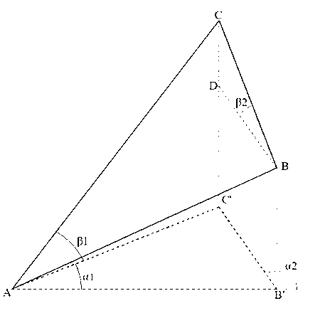
[0014] Such as figure 1 As shown, the present invention utilizes the video monitoring device to monitor target location method, comprises the following steps,

[0015] 1) Control two video monitoring devices that are not on the same straight line as the monitoring target to monitor the monitoring target at the same time, and make the monitoring target located in the center of the video image, where the two video monitoring devices are recorded as PTZ A and cloud station B, mark the monitoring target as target C,

[0016] 2) The control system reads the location information of each video surveillance device and the geographic angle information of the current camera. The location info...


PUM


Abstract

The invention discloses a method for positioning a monitoring target by using video monitoring devices. The method comprises the following steps of 1) controlling the two video monitoring devices which are not located on the same straight line with the monitoring target, and monitoring the monitoring target by using the two video monitoring devices simultaneously; and locating the monitoring target at the center of a video image; 2) reading position information of each video monitoring device and geographic angle information of a current camera by a control system; and 3) calculating to obtain position information of the monitoring target according to the position information and the geographic angle information of each video monitoring device, and outputting the position information of the monitoring target by using the control system. The invention further discloses a positioning device capable of realizing the method simultaneously. According to the positioning method provided by the invention, former monitoring equipment only needs to be slightly improved, so that the function of positioning the monitoring target can be realized. Furthermore, a farther target can be seen through the monitoring equipment, so that the method provided by the invention has the characteristics of low cost, high precision, and far measured distance.

Description

technical field [0001] The invention relates to the technical field of video monitoring, in particular to a method and system for locating a monitoring target by using a video monitoring device. Background technique [0002] The traditional monitoring system uses front-end equipment to collect video data, then transmits it to the back-end monitor through the line, and finally analyzes and processes the image information by humans. With the development of technology, monitoring is no longer satisfied with the only image information, and sometimes it is necessary to know the location information of the monitoring target. It is difficult to locate the target only through the monitoring screen, and the traditional method estimates the target through the zoom and focus of the lens. The location method is not only difficult to operate, but also has low precision, which is difficult to meet the needs of some occasions. Of course, there are also some patents related to target posit...

Claims


Application Information

Patent Timeline
IPC IPC(8): G01C11/36
Inventor 张福明梁如意
Owner TIANJIN YAAN TECH CO LTD
Learn More