
Gas distributor

A gas distributor and distributor technology, used in chemical instruments and methods, feeding devices, chemical/physical processes, etc., can solve the problem of poor gas phase mixing, affecting equipment operation and efficiency, and it is difficult for distributors to achieve uniform distribution of gas, etc. question

Inactive Publication Date: 2015-02-18
NANJING TECH UNIV
View PDF4 Cites 0 Cited by
  • Summary
  • Abstract
  • Description
  • Claims
  • Application Information

AI Technical Summary

Problems solved by technology

When the fixed air holes are used for single gas phase reaction or gas-liquid multi-phase reaction, the reactants are easy to block and coke at the air holes of the gas distributor, affecting normal production
When the diameter of the device is large, due to the problem of the air duct setting, the gas flows out from the openings at different positions at different rates, so it is difficult for this kind of distributor to achieve the purpose of uniform gas distribution.
For large-diameter devices, if the gas phase distribution is uneven, it is very likely to cause gas deviation and short circuit, resulting in uneven gas-liquid contact, or poor gas phase mixing, which seriously affects the operation and efficiency of the equipment.

Method used


Image

  • Gas distributor
  • Gas distributor
  • Gas distributor

Examples


example 1

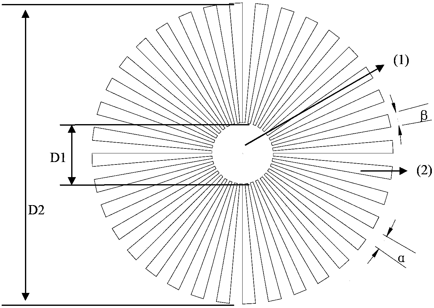
[0016] Example 1: The structure of a single distribution disk is as follows figure 1 As shown, it consists of a baffle and fan-shaped blades. The fan blades surround the baffle in an equidistant annular array. The baffle is a disc with a diameter of D1, which prevents the gas stream from penetrating the equipment for a short time and causing a short circuit. The size of D1 is the same as the inner diameter of the gas inlet pipe of DN600. The inner diameter of the main body of the equipment is 4m, and the outer diameter D2 of the fan-shaped blade is 3.2m. With the baffle as the center, the rotation interval angle α of two adjacent blades is 5°, and the included angle β of the blade itself is 5°. The single distribution plate is made of carbon steel, and the baffle and fan-shaped blades are cut from a single piece of steel plate and installed by installing a bracket at the bottom. Its installation position is set at half of the total height of the gas inlet section of the eq...

example 2

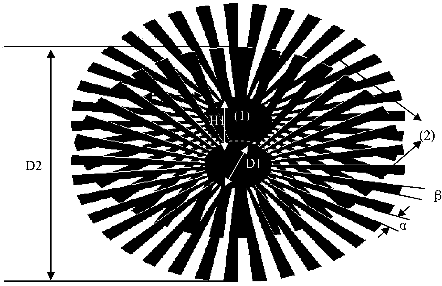
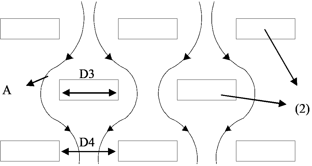
[0017] Example 2: figure 2 It is a schematic diagram of a two-pan gas distributor. For each distribution disc, the rotation interval angle of two adjacent blades is 4°, and the included angle of the blade itself is also 4°. The size of the baffle diameter D1 is the same as the inner diameter of the gas inlet pipe of DN800. The inner diameter of the main body of the equipment is 6m, and the outer diameter D2 of the fan-shaped blade is 5.4m. The forms of the two distribution discs are exactly the same, and the two distribution discs are fixed on a common support shaft, arranged in sequence on the support shaft, and their respective fan-shaped blades and gas channels are interlaced. The distance between the two distribution discs is set H1 to be 1 / 20 of the inner diameter of the inlet pipe. The material of the distributor parts is high-strength alloy steel, the baffle and the fan-shaped blades are fixedly connected by bolts, and the installation method is top hoisting. Where...


PUM


Abstract

The invention relates to a gas distributor. The gas distributor consists of a single distribution plate or a plurality of distribution plates, wherein each distribution plate consists of a gas flow baffle 1 and a fan-shaped blade 2; the fan-shaped blade 2 surrounds the gas flow baffle 1, so as to form an equal-distance annular array; and the gas flow baffle and the fan-shaped blade are located on a same horizontal plane. The distributor provided by the invention has a very good gas distribution effect on equipment with large diameter. Meanwhile, the gas distributor provided by the invention has the advantages of simple structure, convenience in machining and mounting, and large operation elasticity; and the manufacturing, operation and maintenance costs can be effectively saved.

Description

technical field [0001] The invention relates to a gas distributor, in particular to a gas distributor suitable for large-diameter equipment. Background technique [0002] The commonly used gas distributor is a pipe-hole device composed of the main air inlet pipe, the air pipe distributor and the air hole. When the fixed air holes are used for single gas-phase reaction or gas-liquid multi-phase reaction, the reactants are easy to block and coke at the air holes of the gas distributor, affecting normal production. When the diameter of the device is large, due to the problem of the arrangement of the air duct, the rate of gas flowing out from the openings at different positions is different, so it is difficult for this kind of distributor to achieve the purpose of uniform gas distribution. For large-diameter devices, if the gas phase distribution is uneven, it is very likely to cause bias flow and short circuit of the gas, resulting in uneven contact between the gas and liquid...

Claims


Application Information

Patent Timeline
Patent Type & Authority Patents(China)
IPC IPC(8): B01J4/00
Inventor 朱明刘晓勤范益群刘春江
Owner NANJING TECH UNIV
Learn More