Start separation device for engine ignition

A separation device and engine technology, applied in automatic clutches, clutches, mechanical equipment, etc., can solve the problems of low utilization rate of test benches, cumbersome test procedures, and restricting factory production efficiency.

Active Publication Date: 2013-03-06
CAMALUOYANGELECTROMECHANIC
View PDF5 Cites 1 Cited by
  • Summary
  • Abstract
  • Description
  • Claims
  • Application Information

AI Technical Summary

Problems solved by technology

[0003] At present, when conducting a thermal run-in test of an engine with a flywheel friction disc, it is necessary to remove the friction disc first, connect the coupling to the flywheel through a self-made flange, and tighten 6 bolts. The device, such as the motor, drives the engine to ignite, and then disengages the motor through manual intervention. After the test is completed, the bolts and couplings must be disassembled and the friction disc installed. The test process is cumbersome and the auxiliary time is long, which leads to the use of the test bench. The rate is low, restricting the production efficiency of the factory

Method used


Image

  • Start separation device for engine ignition
  • Start separation device for engine ignition
  • Start separation device for engine ignition

Examples


Embodiment Construction

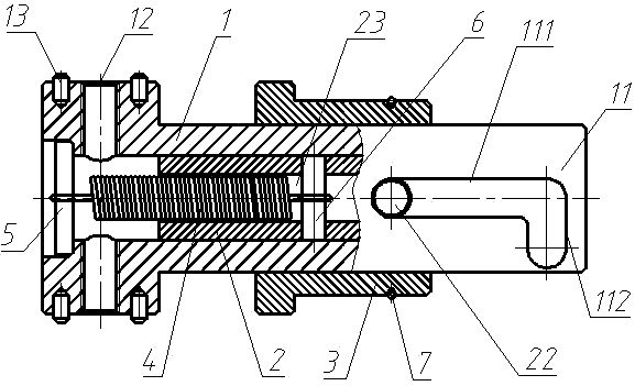
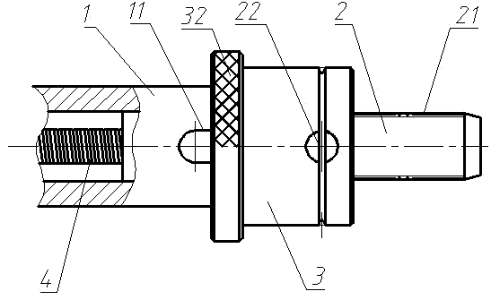
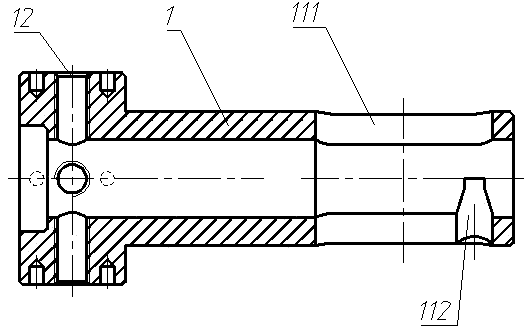
[0023] An embodiment of the starting separation device for engine ignition of the present invention is as Figure 1~Figure 8 As shown, it mainly includes a cylindrical transmission sleeve 1 as a transmission guide, a spline shaft 2 as a sliding joint, a sliding sleeve 3, a tension spring 4 and a retaining spring 7. The starting separation device for engine ignition adopts a variable frequency motor as the engine ignition dragging device, and the output shaft of the variable frequency motor is connected with a shaft coupling. There are four threaded connection holes 12 evenly distributed on the circumferential surface of the rear part of the transmission sleeve 1, and the torque transmission between the shaft coupling and the transmission sleeve 1 is realized through bolts. Four positioning pins 13 are also arranged on the peripheral surface to realize precise positioning of the transmission sleeve 1 and the shaft coupling.

[0024] The front portion of the spline shaft 2 is p...


PUM


Abstract

The invention relates to a start separation device for engine ignition. The start separation device comprises a sliding butt joint part which is provided with a spline on a front part and a transmission guiding part, wherein the rear part of the transmission guiding part is in transmission connection with an ignition dragging device, and the rear part of the sliding butt joint part is in longitudinal oriented assembly and running fit with the front part of the transmission guiding part through a structure that a shaft and a shaft sleeve are in plug bush matching with each other; one of the sliding butt joint part and the transmission guiding part is provided with a guide pin, the other one is provided with a guide slot hole which is in oriented matching with the guide pin, the guide slot hole comprises a flexible section and a limiting section, the flexible section is used for the guide pin to move back and forth so that the sliding butt joint part is stretched out forwards or retracted backwards, the limiting section is in smooth transition connection with the front part of the flexible section and limits the guide pin along the longitudinal direction, the limiting section extends along the relative rotating periphery of the shaft and the shaft sleeve and is used for the forward and backward rotation of the guide pin, and the tail end of the limiting section is provided with a plugging part for stopping and matching with the guide pin which forwardly rotates in place; and a tension spring which applies backward acting force on the sliding butt joint part is connected between the sliding butt joint part and the transmission guiding part. The device is convenient to butt join and can be conveniently separated from an engine after the ignition.

Description

technical field [0001] The invention relates to a starting separation device for engine ignition. Background technique [0002] Before the engine is installed in the vehicle, it is required to carry out the factory test of the engine. For gasoline engines, the engine thermal running-in test bench is generally used to complete the thermal running-in test ranging from a few minutes to several hours. A single test bench needs to complete dozens of sets of tests a day, so the shorter the test auxiliary time, the better. . [0003] At present, when conducting a thermal run-in test of an engine with a flywheel friction disc, it is necessary to remove the friction disc first, connect the coupling to the flywheel through a self-made flange, and tighten 6 bolts. The device, such as the motor, drives the engine to ignite, and then disengages the motor through manual intervention. After the test is completed, the bolts and couplings must be disassembled and the friction disc installe...

Claims


Application Information

Patent Timeline
Patent Type & Authority Applications(China)
IPC IPC(8): F16D43/04
Inventor 薛朋余赵小平程军李小亮杨敬伟
Owner CAMALUOYANGELECTROMECHANIC
Why Eureka
Try Eureka