Method, device and system for light remote positioning

A technology of light and light sensing, applied in the electronic field, can solve problems such as reducing user experience, complexity, and relative position cannot be displayed, and achieve the effect of improving experience

Active Publication Date: 2016-12-21
SHENZHEN SKYWORTH DIGITAL TECH CO LTD +1
View PDF7 Cites 0 Cited by
  • Summary
  • Abstract
  • Description
  • Claims
  • Application Information

AI Technical Summary

Problems solved by technology

[0002] The remote control is a device used to remotely control machinery. The traditional infrared remote control is mainly composed of integrated circuit boards and buttons used to generate different messages. It has the advantage of being simple and easy to use. However, with the development of technology, Some control devices require more and more complex functions to be controlled. For example, the current TV has the functions of web browsing and playing dynamic games, and there are more and more interface elements. Therefore, the traditional remote control can no longer meet the new operation requirements. The infrared remote control itself does not provide positioning capability. Its positioning capability is actually converted into moving information by the operation of the buttons on it, and then changes the position positioning. Its relative position to the screen cannot be displayed. When the user operates Not convenient enough and will degrade user experience

Method used


Image

  • Method, device and system for light remote positioning
  • Method, device and system for light remote positioning
  • Method, device and system for light remote positioning

Examples


Embodiment Construction

[0049] The following will clearly and completely describe the technical solutions in the embodiments of the present invention with reference to the accompanying drawings in the embodiments of the present invention. Obviously, the described embodiments are only some, not all, embodiments of the present invention. Based on the embodiments of the present invention, all other embodiments obtained by persons of ordinary skill in the art without creative efforts fall within the protection scope of the present invention.

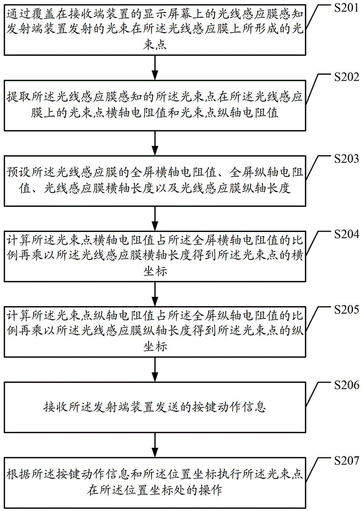
[0050] Embodiments of the present invention provide a method, device and system for light remote positioning, which can obtain the position coordinates of a light beam point through a light sensitive film, so as to realize remote control of interface elements. The following will be described through specific examples.

[0051] see figure 1 , is a schematic flowchart of a first embodiment of a method for optical remote positioning provided by an embodiment of the p...


PUM


Abstract

The embodiment of the present invention discloses a method, device and system for light remote positioning, wherein the method includes the following steps: through the light sensing film covered on the display screen of the receiving end device, the light beam emitted by the transmitting end device is sensed by the light sensor The beam spot formed on the film; extracting the position parameter of the beam spot on the light sensing film sensed by the light sensing film, and calculating the position coordinates of the beam spot through the position parameter. By adopting the invention, the position coordinates of the beam spot can be obtained through the light sensitive film, so as to realize the remote control operation of the interface elements.

Description

technical field [0001] The invention relates to the field of electronic technology, in particular to a method, device and system for optical remote positioning. Background technique [0002] The remote control is a device used to remotely control machinery. The traditional infrared remote control is mainly composed of integrated circuit boards and buttons used to generate different messages. It has the advantage of being simple and easy to use. However, with the development of technology, Some control devices require more and more complex functions to be controlled. For example, the current TV has the functions of web browsing and playing dynamic games, and there are more and more interface elements. Therefore, the traditional remote control can no longer meet the new operation requirements. The infrared remote control itself does not provide positioning capability. Its positioning capability is actually converted into moving information by the operation of the buttons on it...

Claims


Application Information

Patent Timeline
Patent Type & Authority Patents(China)
IPC IPC(8): G06F3/01G06F3/042
CPCG06F3/03542G06F3/0386G06F3/042G06F3/0421H01L31/09H04N21/42204H04N21/42206G06F3/0304G06F3/04892H01L31/101
Inventor 王晓晖毛国红文立夫
Owner SHENZHEN SKYWORTH DIGITAL TECH CO LTD
Why Eureka
Try Eureka