Molding plastic mold for software interface head

A technology for forming plastic molds and software, applied in the field of forming plastic molds, can solve the problems of restricting the development of the plastic industry, increasing hardware costs, increasing production costs, etc., to save human and material resources, improve production efficiency, and improve the effect of yield.

Inactive Publication Date: 2013-02-27
SUZHOU WUZHONG ECONOMIC DEV ZONE BOYU MOLD PROCESSING FACTORY
View PDF2 Cites 15 Cited by
  • Summary
  • Abstract
  • Description
  • Claims
  • Application Information

AI Technical Summary

Problems solved by technology

However, based on the existing mold technology, in order to improve production efficiency, it can only be realized by adding injection molding machines and mold equipment, which will not only increase the hardware cost, but also the corresponding equipment maintenance costs and the consumption of electric energy, water energy and other operating costs. And labor costs are not a small expense. Therefore, the huge increase in production costs has seriously limited the development of the plastics industry.
[0004] The volume and assembly of the existing soft joint tops on the market require that the plastic parts have high dimensional accuracy and molding interface. The existing plastic molds have low molding efficiency and low yield, which greatly increases production costs and wastes resources.

Method used


Image

  • Molding plastic mold for software interface head
  • Molding plastic mold for software interface head
  • Molding plastic mold for software interface head

Examples


Embodiment Construction

[0011] The preferred embodiments of the present invention will be described in detail below in conjunction with the accompanying drawings, so that the advantages and features of the invention can be more easily understood by those skilled in the art, so as to define the protection scope of the present invention more clearly.

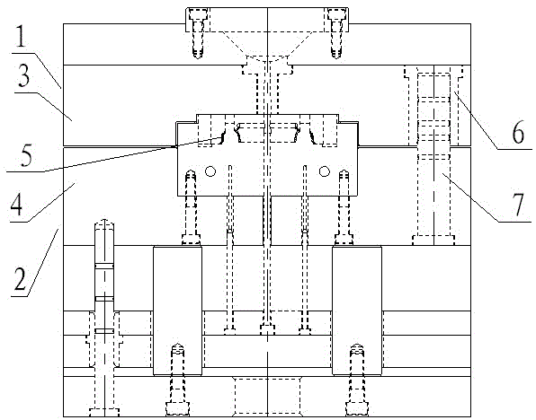
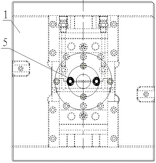
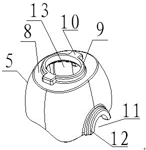
[0012] see Figure 1 to Figure 3 , the embodiment of the present invention includes:

[0013] A plastic mold for forming a soft joint top. The plastic mold for forming a soft joint top includes a fixed mold 1 and a movable mold 2. A guide sleeve 6 is installed on the fixed template 3 of the fixed mold 1, and the guide sleeve 6 is inserted with a movable mold. The movable guide post 7, the guide post 7 is fixed on the movable template 4 of the movable mold 2, and the movable mold 2 performs opening and closing movement through the guide pillar 7; the movable mold 2 and the fixed mold 1 are correspondingly engaged to form two moldings Two forming cavities...


PUM


Abstract

The invention discloses a molding plastic mold for a software interface head. The molding plastic mold disclosed herein comprises a fixed mold, a movable mold, a feed inlet and a cooling water channel, wherein a fixed template of the fixed mold is provided with a guide sleeve, a movable guide pillar is inserted in the guide sleeve, the guide pillar is fixed on a movable template of the movable mold, and the movable mold opens and closes by the guide pillar; the movable mold correspondingly occludes with the fixed mold to form two molding cavities, the two molding cavities are symmetrically arranged along the longitudinal axis of the movable mold, the molding cavity is a hollow frustum-shaped thin plate cavity, the bottom of the frustum-shaped thin plate cavity is an open-ended cavity, the top surface of the frustum-shaped thin plate cavity is provided with a pore cavity, the edge of the pore cavity is provided with an annular boss cavity, and the edge of the annular boss cavity is provided with connected rectangular table cavity. According to the invention, the production process can be simplified, manpower and material resources can be saved, the molding plastic mold disclosed herein is suitable for flow line production of products, the production cost is saved, and the production efficiency of the enterprise is raised.

Description

technical field [0001] The invention relates to a plastic forming mold, in particular to a forming plastic mold for a soft joint top. Background technique [0002] In recent years, with the rapid development and general use of the plastics industry, the strength and precision of engineering plastics have been continuously improved, making the application range of plastic products also expanding, such as household appliances, instruments and meters, construction equipment, automobile industry, Japan, etc. In many fields such as hardware, the proportion of plastic products is increasing rapidly. Plastic mold is a tool for producing plastic products. According to different production processes and products, it can be divided into: injection molding mold, blowing mold, rotational molding mold and thermoforming mold, etc. In the traditional concept, two sets of molds are generally required , because a set of molds has only one parting surface, which constitutes a cavity, and an ...

Claims


Application Information

Patent Timeline
IPC IPC(8): B29C45/26B29C45/32B29C33/30
Inventor 杨理森
Owner SUZHOU WUZHONG ECONOMIC DEV ZONE BOYU MOLD PROCESSING FACTORY
Why Eureka
Try Eureka