
Method and device for detecting biological material

A technology for biomaterials and measurement devices, applied in measurement devices, analytical materials, material excitation analysis, etc., can solve problems such as fragile operation, complex measurement and analysis, etc.

Inactive Publication Date: 2013-02-13
环境学有限公司
View PDF9 Cites 4 Cited by
  • Summary
  • Abstract
  • Description
  • Claims
  • Application Information

AI Technical Summary

Problems solved by technology

In order to work, this solution requires complex electronics for measuring and analyzing the pulse height, which is fragile in the case of high particle content

Method used


Image

  • Method and device for detecting biological material
  • Method and device for detecting biological material
  • Method and device for detecting biological material

Examples


Embodiment Construction

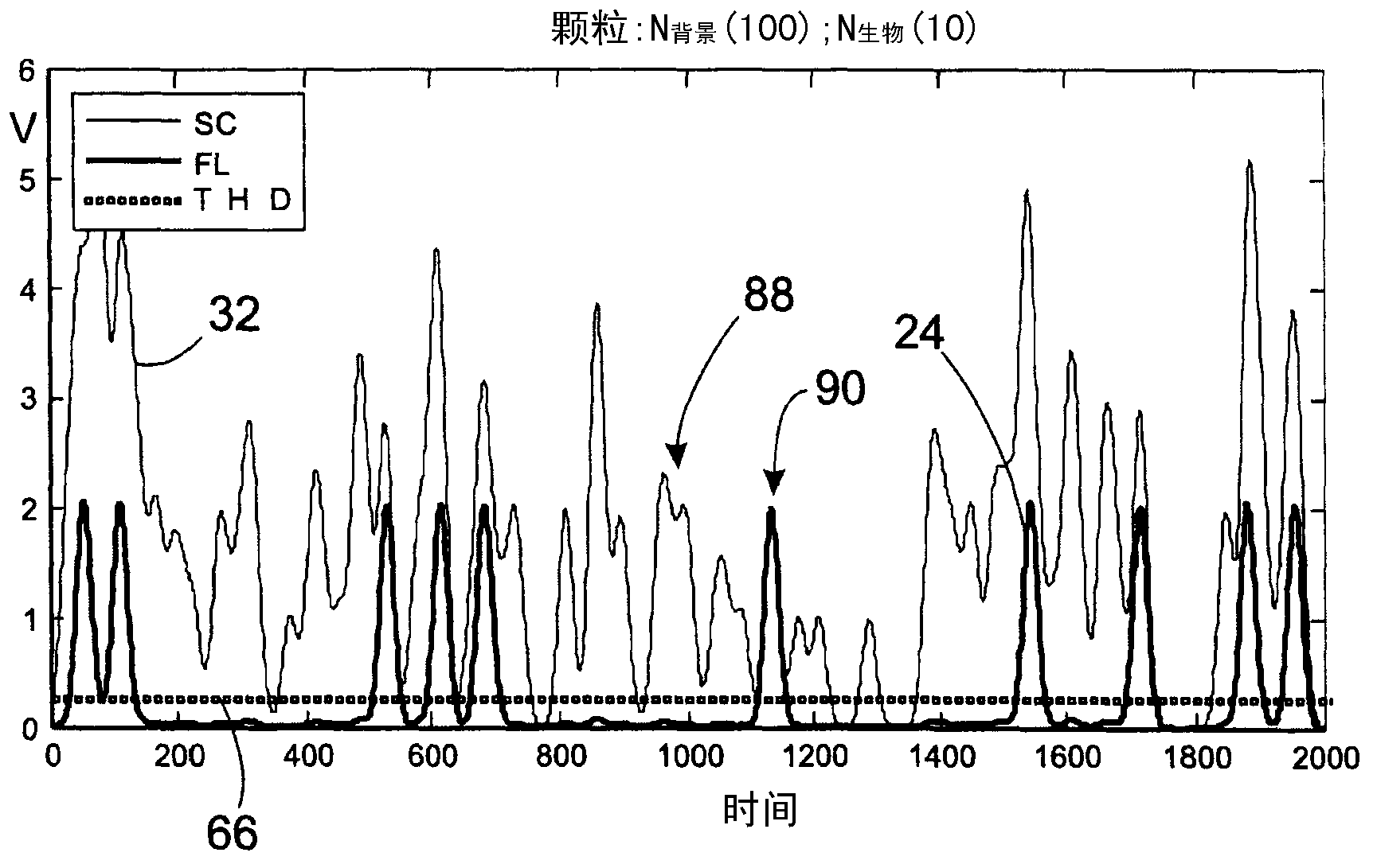
[0044] figure 1 The fluorescence signal 24 and the scatter signal 32 measured using a device according to the prior art are shown. In both curves, individual peaks (eg, peak 90) represent individual particles detected by the device. High scattering peaks are due to large particles, while smaller peaks are due to small particles. The peaks in the fluorescence graphs depict particles containing substances with a large amount of fluorescence. figure 1 Of the many curves shown in , curve SC refers to scatter, FL refers to fluorescence, and THD refers to the trigger level 66, ie the level above which the signal is measured. In prior art devices, biological particles are detected based on peak measurements of fluorescence and scatter signals. It is assumed that individual peaks represent individual bioparticles. The peak value is only measured when it exceeds the trigger level 66.

[0045] However, a problem with this process is that if the air has a high particle content, the ...


PUM

PropertyMeasurementUnit
wavelengthaaaaaaaaaa
sizeaaaaaaaaaa

Abstract

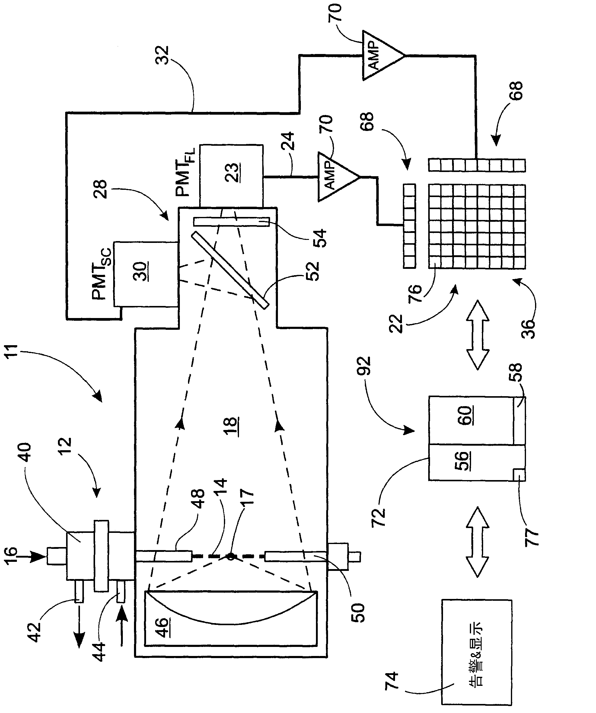
The invention relates to a method for detecting biological material in an airstream, in which method the airstream (16) is fed with the aid of sampling devices (12), a light beam (17) is emitted towards the airstream (16), a fluorescence signal (24) depicting the fluorescence of the particle (14) is created, a scattering signal (32) depicting the scattering of the light of the particle (14) is created, the fluorescence signal (24) and the scattering signal (32) are converted into discrete values, and an alarm value is defined, the discrete values are recorded cumulatively as hit points in an at least 2 - dimension a 1 measurement space equipped with selected dimensions, at least one index area (56, 58, 60) is preselected from the said measurement space, a cumulative index is calculated at an index frequency from the hit points accumulated on the each preselected index area (56, 58, 60), an alarm value, showing the presence of a selected biological material, is de fined from the said indices by using a preselected criterion.

Description

technical field [0001] The present invention relates to a method for detecting biological material in a gas stream containing particles of biological material and / or biologically inert material, in which method: [0002] - the gas flow is fed into the chamber and fed out of the chamber after sampling by means of several sampling devices, [0003] - sending a beam of light towards the airflow by a light source to excite particles in the airflow to produce fluorescence, [0004] - measuring the fluorescence emitted by each particle hit by the beam of light by means of a first measuring device and generating a fluorescence signal delineating the fluorescence of the particle, [0005] - measuring the light scattered by each particle hit by the light beam by means of a second measuring device and generating a scatter signal characterizing the light scattering of the particle, [0006] - conversion of fluorescence and scatter signals to discrete values ​​at the sampling frequency,...

Claims


Application Information

Patent Timeline
Patent Type & Authority Applications(China)
IPC IPC(8): G01N15/14G01N21/53G01N21/64
CPCG01N2021/6493G01N21/6486G01N15/1459G01N21/53G01N21/645G01N15/14G01N33/483G01N21/64
Inventor 考科·延凯约尔马·凯斯基宁马蒂·普特基兰塔桑波·萨里卡特娅·本特松
Owner 环境学有限公司
Learn More