Crane main beam positioning device and method

A positioning device and positioning method technology, applied in transportation and packaging, supporting structures, welding equipment, etc., can solve the problems of crane rail gnawing, difficulties, deformation and positioning of elastic pin shafts, etc., and achieve accurate positioning and reliable quality

Active Publication Date: 2013-02-13
EUROCRANE
View PDF6 Cites 2 Cited by
  • Summary
  • Abstract
  • Description
  • Claims
  • Application Information

AI Technical Summary

Problems solved by technology

Conventional cranes use bolts and pins for positioning. Because the elastic pins are easy to deform, the positioning is inaccurate and the positioning holes are difficult to match.
After a period of use, the elastic pin is easy to fall off, causing the main girder to shift relative to the end girder, causing the crane to gnaw the rail

Method used


Image

  • Crane main beam positioning device and method
  • Crane main beam positioning device and method
  • Crane main beam positioning device and method

Examples


Embodiment

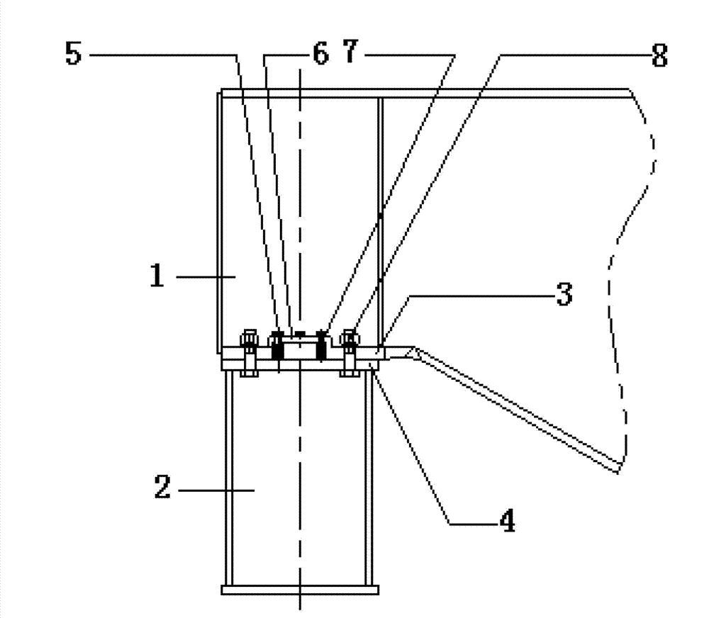
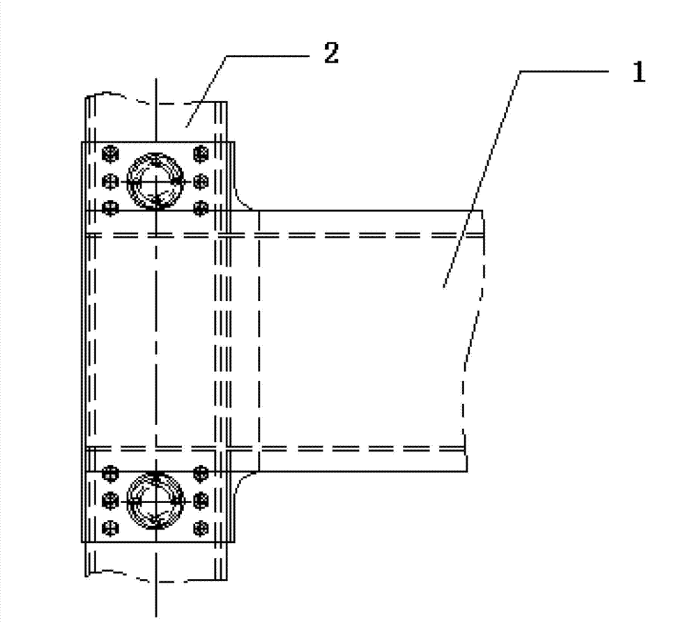
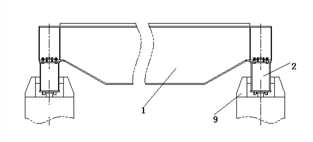
[0022] Example: such as figure 1 , figure 2 , image 3 The main beam positioning device of the crane shown includes the main beam connecting plate 3 and the end beam connecting plate 4, the main beam connecting plate 3 is connected with the main beam 1 through the connecting bolt group 8; the end beam connecting plate 4 is connected with the end beam 2 through the bolt group connected; the connecting plate of the main beam is provided with a positioning hole, and the connecting plate of the end beam is welded with a positioning sleeve 7 matching the positioning hole. A gland 6 is also provided on the main beam connecting plate 3 , and the gland 6 is connected with the main beam connecting plate 3 through the gland bolt group 5 . The positioning sleeve in this embodiment is cylindrical, and may also be in the shape of a truncated cone. The installation steps are as follows:

[0023] (1) Fix the end beam and the end beam connecting plate with the bolt group and put t...


PUM


Abstract

The invention discloses a crane main beam positioning device which is characterized by comprising a main beam connecting board and an end beam connecting board; the main beam connecting board is connected with a main beam through a bolt group; the end beam connecting board is connected with an end beam through a bolt group; a positioning hole is formed in the main beam connecting board; and a positioning sleeve matched with the positioning hole is welded on the end beam connecting board. The crane main beam positioning device overcomes the defects of positioning of the original elastic pin, is accurate in positioning and has a reliable quality.

Description

technical field [0001] The invention relates to a bridge crane, in particular to a crane girder positioning device and method. Background technique [0002] Bridge crane is an important tool and equipment to realize the mechanization and automation of production process in modern industrial production and lifting transportation. Therefore, bridge cranes are widely used in indoor and outdoor industrial and mining enterprises, iron and steel chemical industry, railway transportation, port terminals and logistics turnover and other departments and places. Ordinary bridge cranes are generally composed of a lifting trolley, a bridge running mechanism, and a bridge metal structure. The lifting trolley is composed of three parts: the lifting mechanism, the trolley running mechanism and the trolley frame. The metal structure of the bridge is composed of main girders and end girders, which are divided into two types: single main girder bridge and double girder bridge. The single g...

Claims


Application Information

Patent Timeline
Patent Type & Authority Applications(China)
IPC IPC(8): B66C6/00B23K31/02
Inventor 韩明强张雨徐红圆
Owner EUROCRANE
Why Eureka
Try Eureka