Computer vision cube calibration based three-dimensional measurement method

A computer vision and three-dimensional measurement technology, applied in the field of computer vision, can solve the problems of complex calibration system, inability to obtain measurement results in real time, and expensive system, and achieve the effect of expanding the calibration range, reducing economic costs, and improving calibration accuracy.

Inactive Publication Date: 2013-02-06
SHANGHAI UNIV
View PDF2 Cites 18 Cited by
  • Summary
  • Abstract
  • Description
  • Claims
  • Application Information

AI Technical Summary

Problems solved by technology

[0003] In the field of measurement, although there are mature commercial equipment, its calibration system is complex, requires careful design of the calibration environment, and the entire system is expensive; more importantly, in order to ensure accuracy, vision-based measurement systems often use independent high-level The single-pixel SLR camera is equipped as an image acquisition device, which makes the two processes of image acquisition and measurement must be completed separately, and the measurement results cannot be obtained in real time

Method used


Image

  • Computer vision cube calibration based three-dimensional measurement method
  • Computer vision cube calibration based three-dimensional measurement method
  • Computer vision cube calibration based three-dimensional measurement method

Examples


Embodiment 1

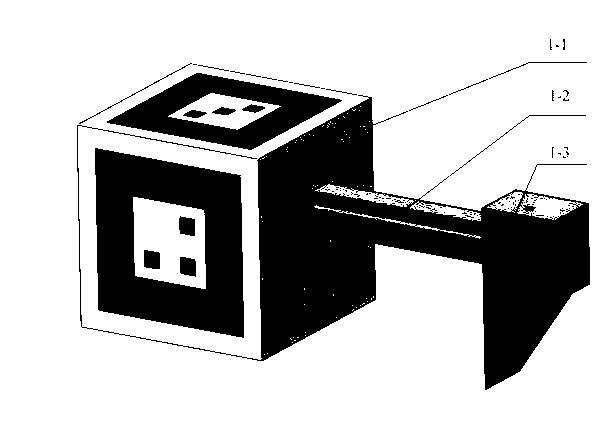
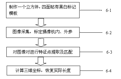
[0021] See figure 1 with image 3 , This three-dimensional measurement method based on computer vision cube calibration is characterized in that it includes the following steps:

[0022] 1) Use a cube with a black and white mark on the surface—a combination pattern of a large black and white box and three small black squares with its own clamping device as a calibration object;

[0023] 2) Use the dot matrix graphic template to calibrate the camera internal parameters, and then use the calibration cube to calibrate the camera external parameters and collect image pairs;

[0024] 3) Use the SIFT method to identify and match the feature points of the acquired image pairs;

[0025] 4) Finally, the three-dimensional coordinates of the key points are calculated and the actual length is restored.

Embodiment 2

[0027] This embodiment is basically the same as the first embodiment, and the special features are:

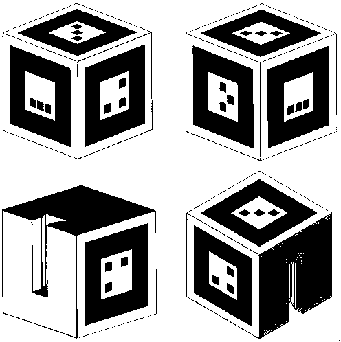
[0028] 1) The black and white marks are a set of templates, and they are different.

[0029] 2) The cube calibration object and its own clamping device are 50*50*50mm 3 , The clamping device can be slid and fixed freely between 0 and 50mm.

[0030] 3) The camera calibration is divided into two independent parts, which internally participate in the calibration of external parameters. Extract multiple images, use the image coordinate system, the world coordinate system and the relationship between the image coordinate system to obtain the projection matrix, and perform QR decomposition of the projection matrix to obtain the internal and external parameters of the camera.

[0031] 4) The center of any black and white mark template of the calibration cube is used as the origin of the three-dimensional coordinates to obtain the transfer matrix when the camera takes pictures, and the...


PUM


Abstract

The invention discloses a computer vision cube calibration based three-dimensional measurement method including the steps: preparing a cube and pasting black and white mark templates (each of the templates comprises a combined pattern of a large black and white square and three small black squares) on the surfaces of the cube; acquiring internal references of a video camera by means of calibration of a calibration plate; extracting an image pair, and computing the calibration cube to obtain external references of the video camera so that calibration of the video camera is completed; performing characteristic point recognition and match for obtained images; and finally, computing three-dimensional coordinates and practical recovery lengths of key points. The three-dimensional measurement method is simple to operate and low in cost, measurement results can be obtained in real time, and application range of three-dimensional measurement is widened.

Description

technical field [0001] The invention relates to the field of computer vision, and relates to a three-dimensional measurement method based on computer vision cube calibration using a cube as a calibration template. Background technique [0002] The ultimate goal of computer vision is to realize the understanding of three-dimensional scenes, that is, to realize some functions of the human visual system. The purpose of computer stereo vision research is to recover 3D scene from 2D projected image. [0003] In the field of measurement, although there are mature commercial equipment, its calibration system is complex, requires careful design of the calibration environment, and the entire system is expensive; more importantly, in order to ensure accuracy, vision-based measurement systems often use independent high-level The single-pixel SLR camera is equipped as an image acquisition device, which makes the two processes of image acquisition and measurement must be completed separ...

Claims


Application Information

Patent Timeline
Patent Type & Authority Applications(China)
IPC IPC(8): G01C11/00G01B11/03G06T7/00
Inventor 张林剑姚远詹航敏黄小虎车雨芳
Owner SHANGHAI UNIV
Why Eureka
Try Eureka