
Double-end-surface mechanical seal

A mechanical seal and double-end technology, applied in mechanical equipment, machines/engines, liquid fuel engines, etc., can solve the problems of increasing the use and maintenance costs of mechanical seals, affecting product quality, and affecting stable production

Inactive Publication Date: 2013-02-06
韩乐工
View PDF6 Cites 9 Cited by
  • Summary
  • Abstract
  • Description
  • Claims
  • Application Information

AI Technical Summary

Problems solved by technology

[0002] In industrial production, especially in petrochemical production, in order to ensure production safety and protect the ecological environment from pollution damage, for those rotating equipment that transport various fluid media, the use of various mechanical seals is often the first choice, because these well-known The mechanical seal has a good sealing effect and can achieve zero leakage, but it is used to transport those unclean, high-temperature, flammable, explosive, toxic and harmful fluid media, or the working conditions are harsh, that is, intermittent operation, easy to evacuate, and easy to vibrate. In order to use these known mechanical seal structures well on the equipment, it is necessary to add an oil sealing system, so that these known mechanical seals can achieve better results, which not only increases the cost of using and maintaining the mechanical seals , and it has not essentially eliminated the known safety hazards that the end faces of mechanical seals are easy to open or the bellows will break, especially on high-temperature oil pumps. If the end face is opened too much, the seal oil will leak too much to the external environment. For a safety accident such as a fire, it is not acceptable to leak too much sealing oil into the equipment. This will not only affect the quality of the product, but also cause the equipment to evacuate and cause fluctuations in the production process, which will affect stable production and cause operational accidents.

Method used


Image

  • Double-end-surface mechanical seal
  • Double-end-surface mechanical seal
  • Double-end-surface mechanical seal

Examples


Embodiment Construction

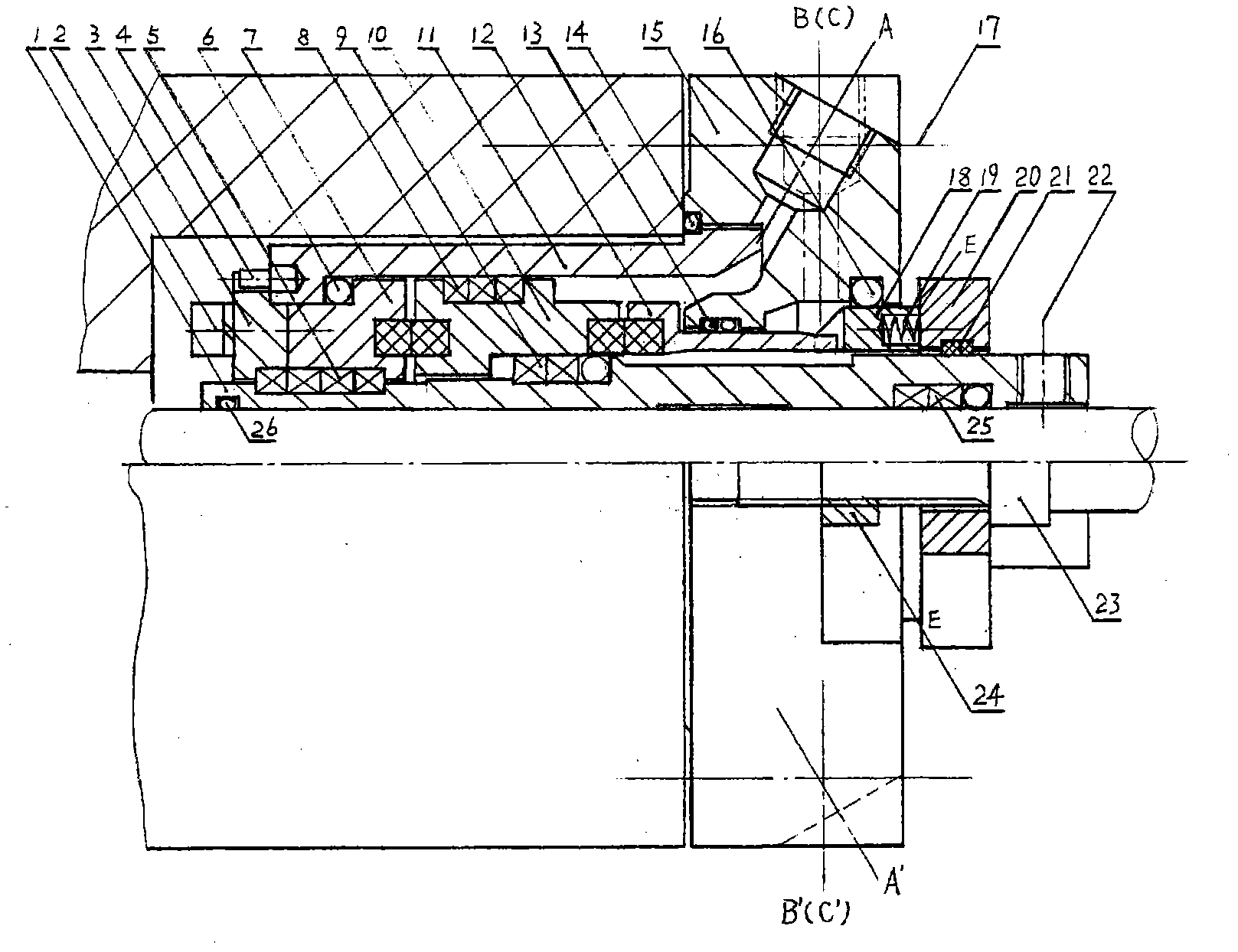
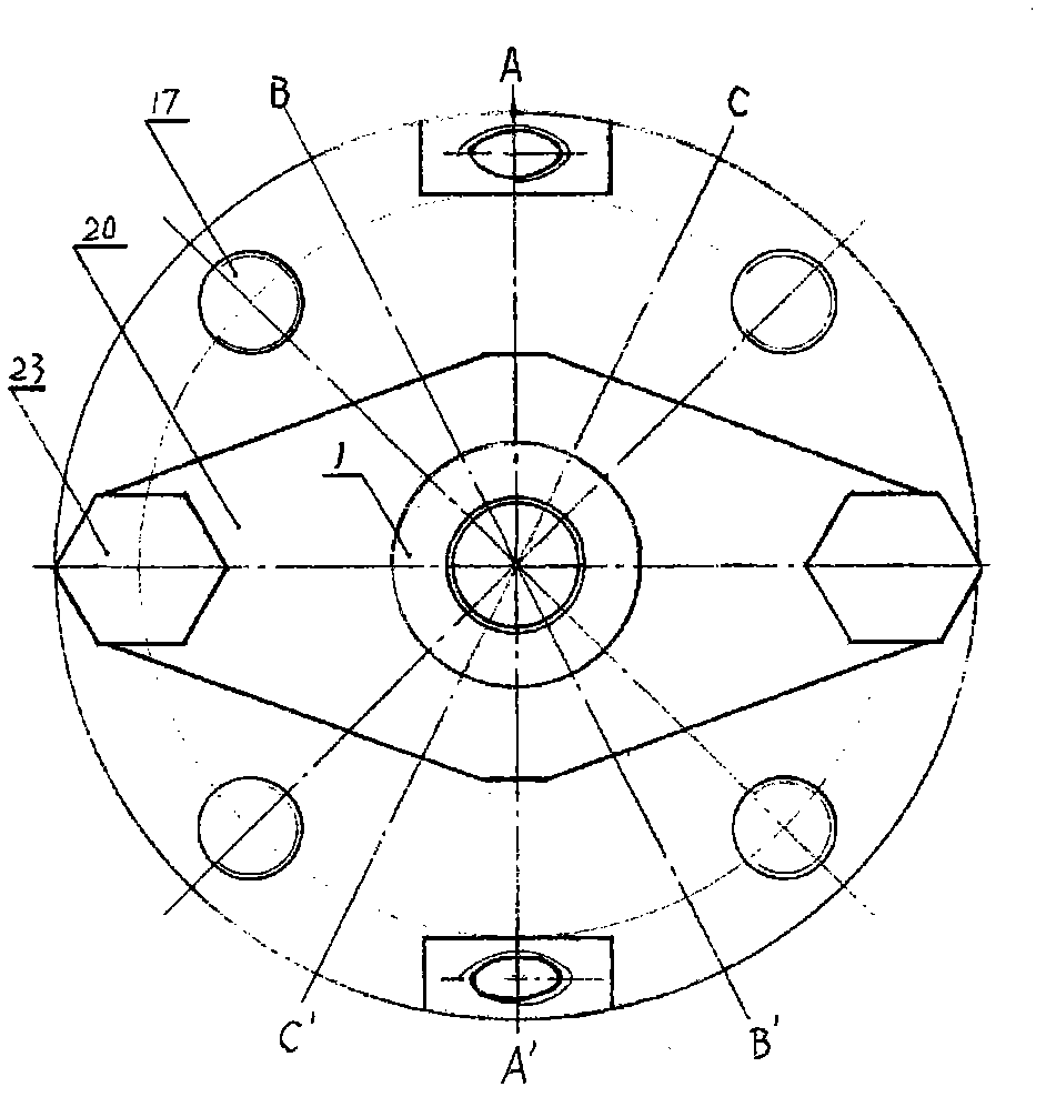
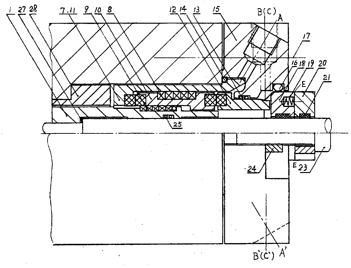
[0015] Below in conjunction with accompanying drawing, the present invention will be further described; figure 1 Shown is a schematic diagram of the standard structure of the double-end mechanical seal part of the entire equipment. The gland 15 is fixed on the stationary equipment body with gland bolts 17 and the gland sealing ring 16 is pressed tightly to prevent the sealed medium from leaking from here. The shaft sleeve 1 is fixed on the rotating shaft of the equipment with the shaft sleeve set screw 22 and rotates with the shaft. The shaft sleeve sealing ring assembly 25 and the front end sealing ring 26 of the shaft sleeve can effectively prevent the sealed medium from coming between the shaft sleeve and the shaft. Leakage in the radial gap, the static ring 7, the moving ring 10 and the compensation ring 12 are installed in series in the closed annular space composed of the sealing sleeve 11, the gland 15, the spring seat 18 and the shaft sleeve 1. The ring set screw 2 loc...


PUM


Abstract

The invention provides a double-end-surface mechanical seal. The standard structure of the double-end-surface mechanical seal comprises a positioning packing structure, a double-end-surface sealing structure and a positioning and locking structure. A movable ring (10) rotates along with a shaft sleeve (1) under the action of a shifting fork and can simultaneously slide along an excircle surface of the shaft sleeve front and back (or left and right) in the axial direction, so that the movable ring can be permanently kept in place when the shaft sleeve moves front and back, axial floating of the movable ring is realized and a left end surface clearance and a right end surface clearance formed by the movable ring with a static ring (7) and a compensating ring (12) throughout keep working states. The double-end-surface mechanical seal has the advantages of good sealing effect and wide use range, can realize safe, reliable and long-life operation without using sealing oil or by using little sealing oil, and can simultaneously reduce use costs and maintenance costs of the double-end-surface mechanical seal and bring great social benefits to a user.

Description

technical field [0001] The invention relates to a mechanical seal for a rotating shaft, in particular to a double-face mechanical seal. Background technique [0002] In industrial production, especially in petrochemical production, in order to ensure production safety and protect the ecological environment from pollution damage, for those rotating equipment that transport various fluid media, the use of various mechanical seals is often the first choice, because these well-known The mechanical seal has a good sealing effect and can achieve zero leakage, but it is used to transport those unclean, high-temperature, flammable, explosive, toxic and harmful fluid media, or the working conditions are harsh, that is, intermittent operation, easy to evacuate, and easy to vibrate. In order to use these known mechanical seal structures well on the equipment, it is necessary to add an oil sealing system, so that these known mechanical seals can achieve better results, which not only in...

Claims


Application Information

Patent Timeline
IPC IPC(8): F04D29/10
Inventor 韩乐工
Owner 韩乐工
Learn More