Binocular vision-based robot target identifying and gripping system and method
A target recognition and binocular vision technology, applied in the field of robotics, can solve the problems of service robots with single functions, inability to complete actions, and service robots that cannot navigate autonomously
- Summary
- Abstract
- Description
- Claims
- Application Information
AI Technical Summary
Problems solved by technology
Method used
Image
Examples
Embodiment 1
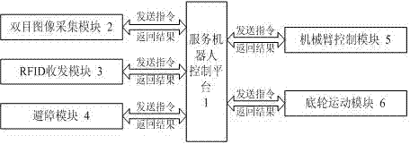
[0053] Such as figure 1 As shown, this service robot target recognition and grasping system based on binocular vision, the service robot control platform (1) is connected to the binocular image acquisition module (2), RFID transceiver module (3), chassis motion module (6) , a barrier module (4) and a robotic arm control module (5).
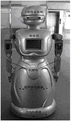
[0054] The binocular image acquisition module (2) refers to the binocular stereo vision system in this system; the RFID transceiver module (3) is a passive radio frequency tag, which contains information such as the position and characteristics of the item; The above-mentioned chassis movement module (6) adopts a two-wheel differential method, and two color sensors are installed at the bottom; the above-mentioned obstacle avoidance module (4) uses multiple ultrasonic and multiple photoelectric sensors, which are respectively installed on the abdomen of the robot and the bottom skirt to detect obstacles at different heights; the humanoid manipulat...
Embodiment 2
[0057] Such as image 3 As shown, the service robot target recognition and grasping method based on binocular vision is operated by using the above system, and it is characterized in that it includes the following steps:
[0058] 1) Binocular camera calibration. Use the plane template method to calibrate the binocular camera of the binocular image acquisition module (2), obtain the internal parameters of the camera, and convert the coordinate values of the target object in the image coordinate system to the target object in the right eye of the binocular camera The coordinate value in the spatial coordinate system of the origin.
[0059] 2) Coordinate system construction and conversion. A space coordinate system is established with the right shoulder of the robot as the coordinate origin, and the coordinate values of the target object in the coordinate system with the right eye as the origin are converted to the coordinate values in the coordinate system.
[0060]...
Embodiment 3
[0092] In this embodiment, the home environment is simulated to realize that the robot can intelligently serve human beings. This embodiment includes the following steps:
[0093] In the first step, in the experimental environment of this embodiment, the binocular camera of the robot is calibrated by using the planar template method to obtain the internal parameters of the camera. The threshold value of the color of the target object in the HSV color space is learned offline; and the threshold value of the outline size of the target object in the image is learned offline when the most accurate coordinate value of the target object is obtained. After the system initialization is completed, the search for the target object is started.
[0094] In the second step, the robot starts to search for the target object at any position in the laboratory, continuously collects images through the binocular camera, performs color space conversion on the pixels in the image, and...
PUM
 Abstract
Description
Claims
Application Information
 - R&D
- Intellectual Property
- Life Sciences
- Materials
- Tech Scout
- Unparalleled Data Quality
- Higher Quality Content
- 60% Fewer Hallucinations
Browse by: Latest US Patents, China's latest patents, Technical Efficacy Thesaurus, Application Domain, Technology Topic, Popular Technical Reports.
© 2025 PatSnap. All rights reserved.Legal|Privacy policy|Modern Slavery Act Transparency Statement|Sitemap|About US| Contact US: help@patsnap.com


