
High-speed pill imaging system

An imaging system and projectile technology, which are used in the diagnosis of high-speed flying projectiles in the field of fusion, and in the field of object imaging systems, can solve problems such as the inability to shoot projectiles from multiple angles and continuous multiple projectiles, and achieve the effect of an effective shooting method.

Active Publication Date: 2015-04-29
SOUTHWESTERN INST OF PHYSICS
View PDF4 Cites 0 Cited by
  • Summary
  • Abstract
  • Description
  • Claims
  • Application Information

AI Technical Summary

Problems solved by technology

[0003] In the past shooting of projectiles, only a single position can be taken, and multi-angle shooting of projectiles and continuous multi-shot shooting of projectiles cannot be realized.

Method used


Image

  • High-speed pill imaging system
  • High-speed pill imaging system
  • High-speed pill imaging system

Examples


Embodiment Construction

[0016] The present invention will be further described below in conjunction with accompanying drawing and specific embodiment:

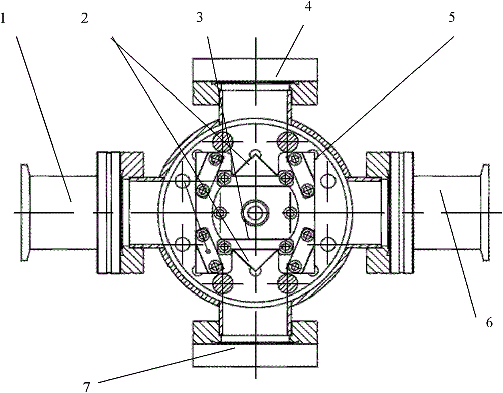
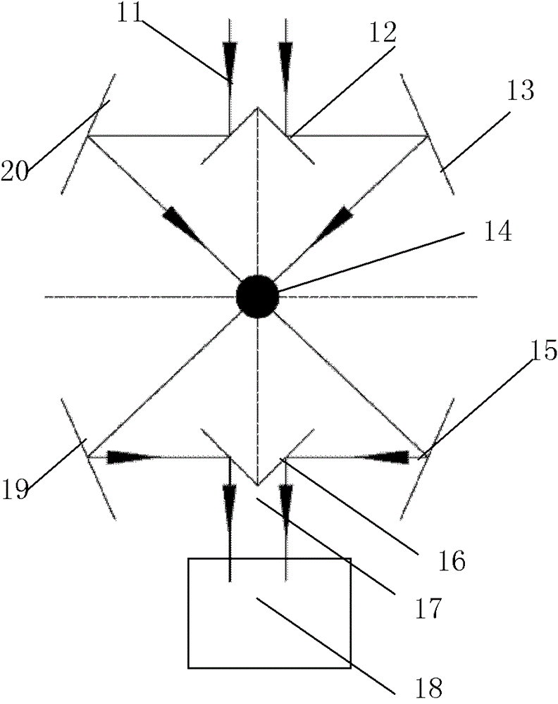
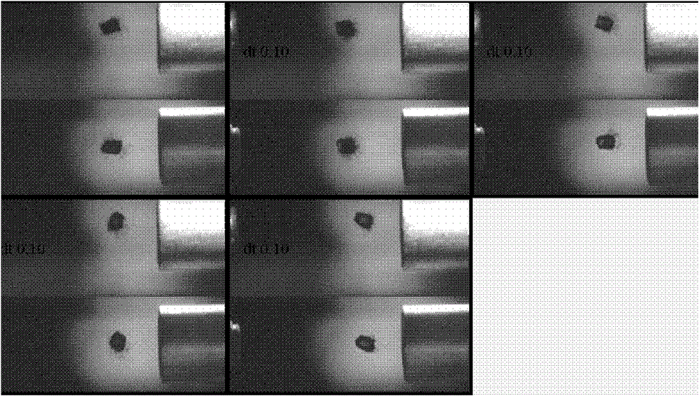
[0017] The high-speed projectile imaging system includes: CCD camera, flash light (light source), mirror system, counter, vacuum observation window, video capture card, etc. The imaging system can be used to take pictures of high-speed projectiles, which provides a good monitoring method for high-speed flying projectiles. The schematic diagram of the installation structure is as follows figure 1 shown. In a "ten"-shaped vacuum chamber, each prism is fixed on the prism bracket, and the four ports of the "ten"-shaped vacuum chamber are sealed with flanges and optical glass. One observation window is equipped with a CCD camera for taking pictures of flying projectiles. ; The other observation window is provided with a flash light to provide a light source; the rest of the observation windows are convenient for observing the position of the imaging syst...


PUM


Abstract

The invention belongs to the field of charging fusion pills, and relates to a high-speed pill imaging system. The invention aims to provide a simple and effective shooting manner aiming at high-speed flying pill imaging. The high-speed pill imaging system comprises a CCD (Charge Coupled Device) camera, a light source and observing windows, and further comprises a cross vacuum chamber; a flying orbit of a pill is vertical with a cross; the two observing windows of the cross vacuum chamber are sealed by flanges and optical glass; one of the observing windows is provided with the CCD camera, and is used for shooting the flying pill; and a flashlight is mounted on the other observing window corresponding to the CCD camera for supplying light power. The high-speed pill imaging system has the advantages that the image of a small transparent object which flies at a high speed can be captured in time; and the continuous multiple pills can be shot at multiple angles.

Description

technical field [0001] The invention belongs to the field of fusion projectile feeding, and relates to an object imaging system, in particular to the diagnosis of high-speed flying projectiles in the field of fusion. Background technique [0002] In the projectile feeding physical experiment of the fusion device, by monitoring and analyzing the speed and photos of the high-speed projectile during flight, it has become an effective means to judge the formation of the projectile and whether it is broken or not. Indispensable data for the relationship; projectile photos can qualitatively measure the size of the projectile, and at the same time explore the preparation conditions of the projectile. [0003] In the previous shooting of projectiles, only single position shooting can be realized, and multi-angle shooting of projectiles and continuous multi-shot shooting of projectiles cannot be realized. [0004] Multi-angle and continuous multi-shot projectile photography can bett...

Claims


Application Information

Patent Timeline
Patent Type & Authority Patents(China)
IPC IPC(8): G03B39/00G03B15/05G02B17/04
Inventor 徐红兵刘德权朱根良王明建
Owner SOUTHWESTERN INST OF PHYSICS
Learn More