Annular vortex coupler

A ring-shaped eddy current coupler technology, applied in the field of mechanical transmission, can solve the problems of large radial size of disc-shaped eddy current coupler, increased construction period and difficulty of work, low stability, etc., achieves small wind resistance, reduces engineering expenses, increases Effects on Reliability and Stability

Inactive Publication Date: 2013-01-23
SHANGHAI POTEVIO
View PDF1 Cites 1 Cited by
  • Summary
  • Abstract
  • Description
  • Claims
  • Application Information

AI Technical Summary

Problems solved by technology

[0003] The actual technical problem to be solved in the present invention is: the radial size of the disc-shaped eddy current coupler is large, if the center height of the equipment used is not high enough, the base needs to be modified, which increases the construction period and work difficulty; An axial force will be generated, and a set of thrust bearings 7 must be provided to support the axial force. The cost is high and the stability is not high; when the heat dissipation element on the sealing plate 8 rotates, a large wind resistance is generated, resulting in a decrease in efficiency and energy efficiency. Increased consumption

Method used


Image

  • Annular vortex coupler
  • Annular vortex coupler
  • Annular vortex coupler

Examples


Embodiment ( 1

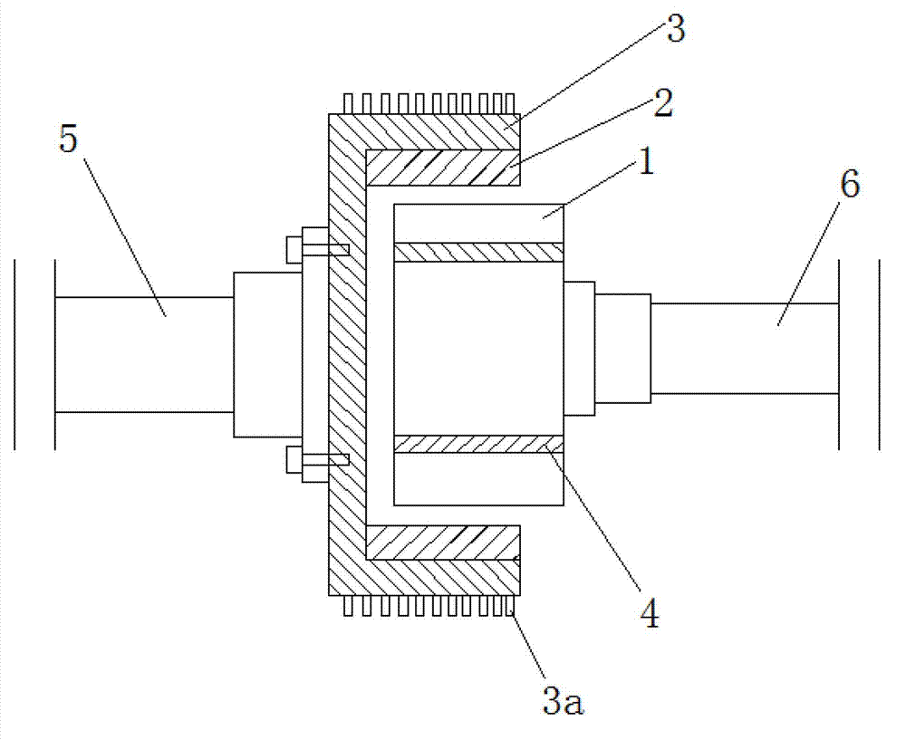
[0020] Such as image 3 As shown, the drive shaft 5, the annular eddy current coupler, and the load shaft 6 are arranged coaxially. The annular coupler includes a first carbon steel ring 3 that plays a supporting role. The axial section of the first carbon steel ring 3 is in a U-shaped structure. The word opening faces to the right, the upper and lower inner walls of the first carbon steel ring 3 are connected to the conductor ring 2, that is, the conductor ring 2 is fixed on the upper and lower inner walls of the first carbon steel ring 3, and the left end of the load shaft 6 is connected to the second carbon steel ring 4 , the permanent magnet ring 1 is fixed on the outside of the second carbon steel ring, and is facing the conductor ring 2. The outer outer surface of the first carbon steel ring 3 is provided with radially arranged cooling fins 3a, and the direction of the cooling fins is parallel to the rotation plane of the first carbon steel ring 3, that is, the direction...

Embodiment ( 2

[0024] On the basis of the first embodiment, the functions of the present invention can also be realized by exchanging the positions of the conductor ring 2 and the permanent magnet ring 1 .

Embodiment ( 3

[0026] On the basis of the first embodiment, after the positions of the drive shaft 5 and the load shaft 6 are reversed, the functions of the present invention can still be realized.


PUM


Abstract

The invention relates to a vortex coupler, and in particular relates to an annular vortex coupler. The annular vortex coupler comprises a driving shaft (5), a load shaft (6) and a rotor component, wherein the driving shaft (5), the load shaft (6) and the rotor component are coaxially arranged. The annular vortex coupler is characterized in that the rotor component comprises a first carbon steel ring (3), wherein the middle axial surface of the first carbon steel ring (3) is [-shaped; the driving shaft (5) is fixedly connected with the outer end face of the first carbon steel ring (3); the inner side face of the first carbon steel ring (3) is attached to conductor rings (2); the rotor component also comprises permanent magnet rings (1) which are arranged at the inner sides of the conductor rings (2) and correspond to the conductor rings (2); one end face of each permanent magnet ring (1) corresponds to the inner end face of the first carbon steel ring (3), and the other end face of each permanent magnet ring (1) is fixedly connected with the load shaft (6); and the inner sides of the permanent magnet rings (1) are attached to second carbon steel rings (4).

Description

technical field [0001] The invention relates to an eddy current coupler, in particular to an annular eddy current coupler, which belongs to the technical field of mechanical transmission. Background technique [0002] Existing eddy current couplers are generally disc-shaped. For example, the application number is 201120133126.8, and the authorized announcement date is December 21, 2011. The Chinese invention patent named "eddy current transmission" discloses an eddy current coupler. Both the conductor rotor assembly and the magnetic rotor assembly of the coupler are disc-shaped, and the radial dimension of the disc-type eddy current coupler is relatively large. If the center height of the equipment used is not high enough, the base needs to be modified, which not only increases the modification cost, but also increases the The construction period and work difficulty are shortened, and the payback period for energy saving of the modified equipment is also extended; when the d...

Claims


Application Information

Patent Timeline
Patent Type & Authority Applications(China)
IPC IPC(8): H02K51/00
Inventor 王允强袁吾均华敏张文奇杨奕
Owner SHANGHAI POTEVIO
Why Eureka
Try Eureka