
Radar power signal-to-noise ratio in-situ testing method

A test method and technology of receiving signal-to-noise ratio, applied to radio wave measurement systems, instruments, etc.

Inactive Publication Date: 2013-06-05
中国人民解放军海军航空仪器计量站
View PDF4 Cites 0 Cited by
  • Summary
  • Abstract
  • Description
  • Claims
  • Application Information

AI Technical Summary

Problems solved by technology

[0008] In order to achieve the above goals, a set of in-situ test methods for receiving signal-to-noise ratio and radiated power outside the cover has been researched and developed, which solves the problem of in-situ inspection of radar transmitters, receivers and antenna feeder systems in the field without dismantling the radar unit. Technical Difficulties Whether It Works

Method used


Image

  • Radar power signal-to-noise ratio in-situ testing method
  • Radar power signal-to-noise ratio in-situ testing method

Examples


Embodiment Construction

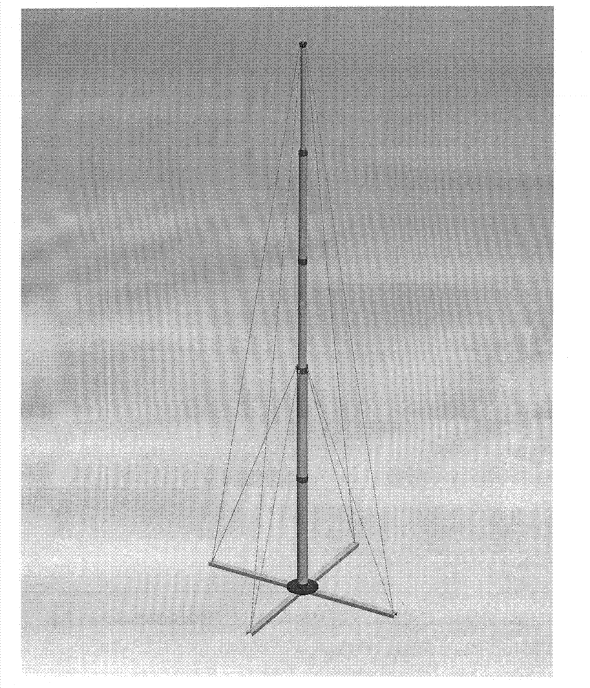
[0026] Schematic diagram of on-site use see figure 1 , the specific test process is as follows:

[0027] a. Set up the lifting antenna about 30 meters in front of the radar antenna. In order to ensure that the radar antenna is raised by more than 5 degrees, the lifting antenna is generally raised to about 6 meters. Align the radar antenna;

[0028] b. Connect the radio frequency cable between the horn antenna and the external tester;

[0029] c. Connect the serial cable between the notebook and the radar data processor;

[0030] d. Turn on the notebook and run the test program;

[0031] e. Turn on the power of the tester outside the enclosure;

[0032] f. Turn on the radar;

[0033] g. The test program controls the radar to enter the noise statistical state, and obtains the noise level data when the radar has no signal; (the statistical noise level is 1.02)

[0034] h. The test program controls the radiation radio frequency signal of the external tester;

[0035] i. The...


PUM


Abstract

The invention provides an in-situ outside-casing testing method which overcomes the shortcoming that radar built-in-test (BIT) cannot detect an antenna feed system. By means of a radar power signal-to-noise ratio in-situ testing method, the testing direction is determined through cross scanning, the signal-to-noise ratio is evaluated through a frequency spectrum mode, and outside-casing radiationpower can be accurately measured through a fixed-point high pressure exerting mode. By means of the radar power signal-to-noise ratio in-situ testing method, the shortcomings of the radar BIT are effectively overcome, the antenna feed system of a radar can be checked during maintenance in ordinary time, failure caused by the antenna feed system on the ground is timely removed, and the failure problem that after the radar screened by the method in the sky cannot find the distance descends or cannot find objects is solved. By means of the radar power signal-to-noise ratio in-situ testing method, the antenna feed system failure which cannot be detected by the radar BIT can be removed, and success rate of an airplane executing a task is greatly improved.

Description

technical field [0001] The invention relates to a test method for directly testing radar receiving signal-to-noise ratio and radiation power outside the cover without dismantling the radar cover. Background technique [0002] At present, the airborne radar has been able to provide a relatively complete BIT self-inspection function, which can cover about 97% of the entire system, and can perform function, performance testing and fault detection on the entire radar system except the antenna feeder system during use and maintenance. [0003] However, since the radar BIT still has a 3% blind spot, that is, it cannot cover the antenna feed system of the radar, which brings many uncertainties to the daily use of various types of airborne radars. Often the radar BIT on the ground is normal, but when the aircraft is flying, it is found that the target cannot be intercepted or the radar range is seriously reduced. This kind of failure may not cause too much damage in normal times, t...

Claims


Application Information

Patent Timeline
Patent Type & Authority Patents(China)
IPC IPC(8): G01S7/40
Inventor 赵一倩
Owner 中国人民解放军海军航空仪器计量站
Learn More