
Aeration pump

A technology of aeration pump and air guide shaft, which is applied in water aeration, pump, pump device, etc., can solve the problems of the air volume and strength of the sieve is not very large, the efficiency is not very ideal, and the path is long.

Active Publication Date: 2013-01-02
浙江灏宇科技有限公司
View PDF9 Cites 0 Cited by
  • Summary
  • Abstract
  • Description
  • Claims
  • Application Information

AI Technical Summary

Problems solved by technology

This kind of device requires the operator to be able to accurately control the amount of compressed air and water flow, so that the operation requirements are high and it is difficult to debug
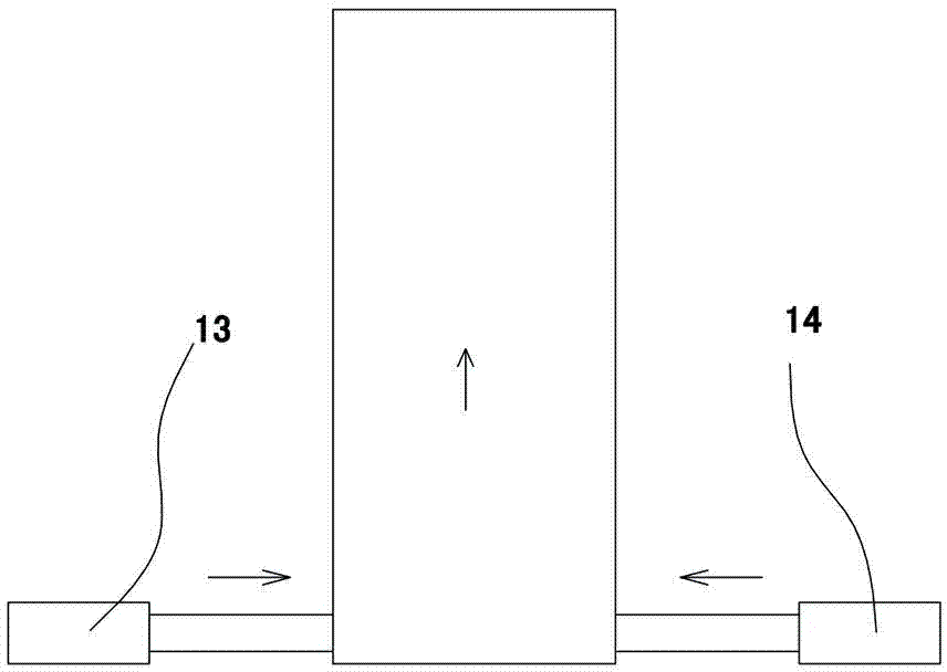
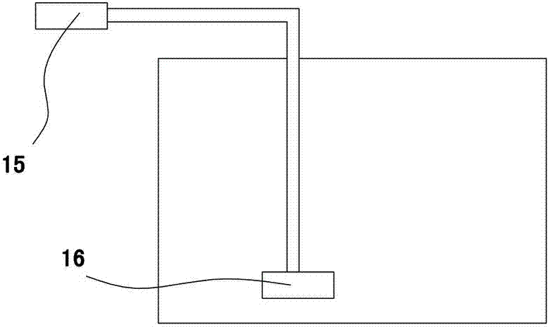
[0003] Please refer to figure 2 , figure 2 The aeration pump in the aeration pump uses the compressed air pump 15 to drive the compressed air into the sieve device 16 in the wastewater tank to generate air bubbles. The tubes used in this aeration device are generally more than 2 meters long, so that the air flows through The path of the sieve is long, so the amount and strength of the air that finally flows into the sieve is not very large, and most of the generated air bubbles do not meet the requirements, and the efficiency is not very ideal.

Method used


Image

  • Aeration pump
  • Aeration pump
  • Aeration pump

Examples


Embodiment Construction

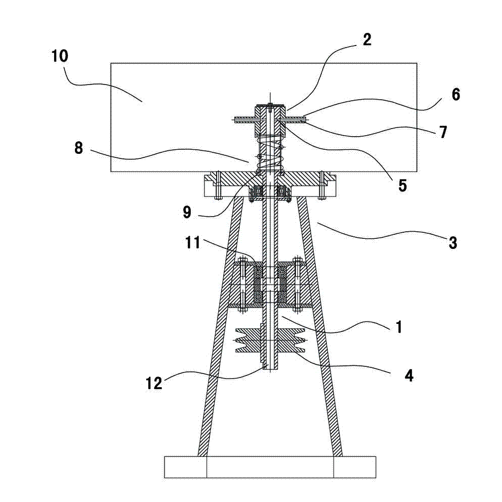
[0014] Please refer to image 3 , the aeration pump in the figure includes a rotary drive device, a hollow wind guide shaft 1, an impeller 2 communicating with the hollow wind guide shaft inner cavity 12, a sealing assembly, and a bracket 3 supporting the above-mentioned components.

[0015] Rotary driving device comprises motor, transmission belt, transmission wheel 4, and wherein motor and transmission belt are not shown in the figure;

[0016] The wind guide shaft 1 is a straight shaft, the inside is empty for outside air to flow in, and the top end is processed with a transverse cavity 5 communicating with the blade cavity 7 of the impeller 2 .

[0017] The impeller 2 includes a hollow inner cavity and a hollow blade 6; the hollow inner cavity is used for installing the wind guide shaft 1, and the blade inner cavity 7 is also hollow and communicates with the transverse cavity 5 of the wind guide shaft 1, and the blade inner cavity 7 forms a height difference with the ...


PUM


Abstract

The invention discloses an aeration pump which comprises a rotary drive device, a hollow air guide shaft, an impeller communicated with the inner cavity of the hollow air guide shaft, a sealing component and a support for supporting the parts above. The air guide shaft is disposed on the rotary drive device. The bottom end of the air guide shaft is communicated with external air. The top end of the air guide shaft is communicated with the inner cavity of the impeller. The impeller comprises a hollow inner cavity and hollow vanes. The hollow inner cavity is communicated with the hollow vanes. The sealing component is disposed on the air guide shaft and connected with a wax water and wastewater tank in a sealed manner. The support is fixed below the wax water and wastewater tank. The air guide shaft and the impeller are driven to rotate by the rotary drive device to generate centrifugal force so as to allow the air to enter the impeller from the bottom end of the air guide shaft, the air then flows into the wax water and wastewater tank to generate bubbles so as to achieve aeration. The aeration pump is capable of generating bubbles simply and efficiently.

Description

technical field [0001] The invention relates to a device for generating air bubbles in a wax water wastewater pool in the printing and dyeing industry. Background technique [0002] Please refer to figure 1 , the aeration pump in the figure uses compressed air 13 to act on the water flowing out from the water pump 14 in the compressed container to generate liquid-gas mixing. This device requires the operator to be able to accurately control the amount of compressed air and water flow, which makes the operation more demanding and difficult to debug. [0003] Please refer to figure 2 , figure 2 The aeration pump in the aeration pump uses the compressed air pump 15 to drive the compressed air into the sieve device 16 in the wastewater tank to generate air bubbles. The tubes used in this aeration device are generally more than 2 meters long, so that the air flows through The path of the sieve is long, so that the amount and strength of the air that finally flow...

Claims


Application Information

Patent Timeline
Patent Type & Authority Applications(China)
IPC IPC(8): F04D25/08F04D29/00F04D29/08C02F7/00
CPCY02W10/10
Inventor 王文龙章元春
Owner 浙江灏宇科技有限公司
Learn More