Screed plate frame and screed plate and paver

A screed frame and screed technology, which is applied in the fields of screed frame, screed and paver, can solve the problems of easy torsion and deformation of the screed frame, and achieve the effects of saving production cost, simple structure and reducing labor intensity

Active Publication Date: 2012-12-26
SANY HEAVY IND CO LTD (CN)
View PDF6 Cites 1 Cited by
  • Summary
  • Abstract
  • Description
  • Claims
  • Application Information

AI Technical Summary

Problems solved by technology

[0007] In view of this, the present invention proposes a method to solve the problem that the existing screed frame is easy to twist and deform

Method used


Image

  • Screed plate frame and screed plate and paver
  • Screed plate frame and screed plate and paver
  • Screed plate frame and screed plate and paver

Examples


Embodiment 1~ Embodiment 12

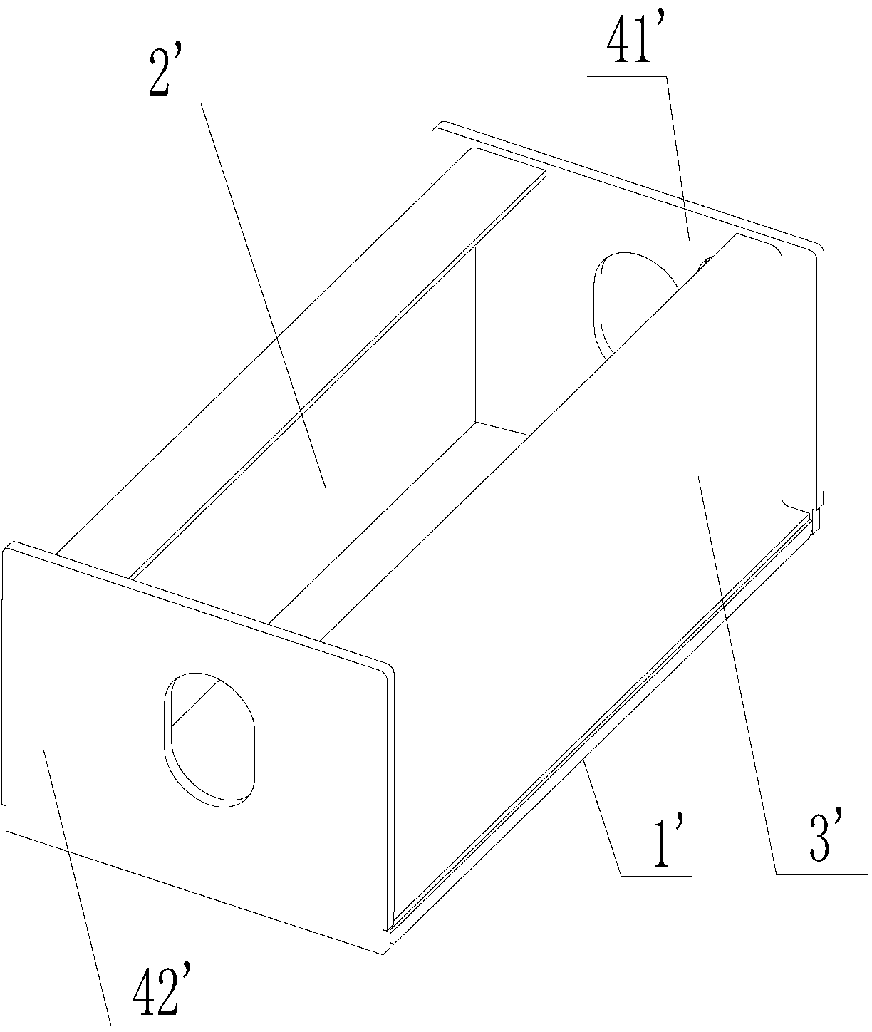
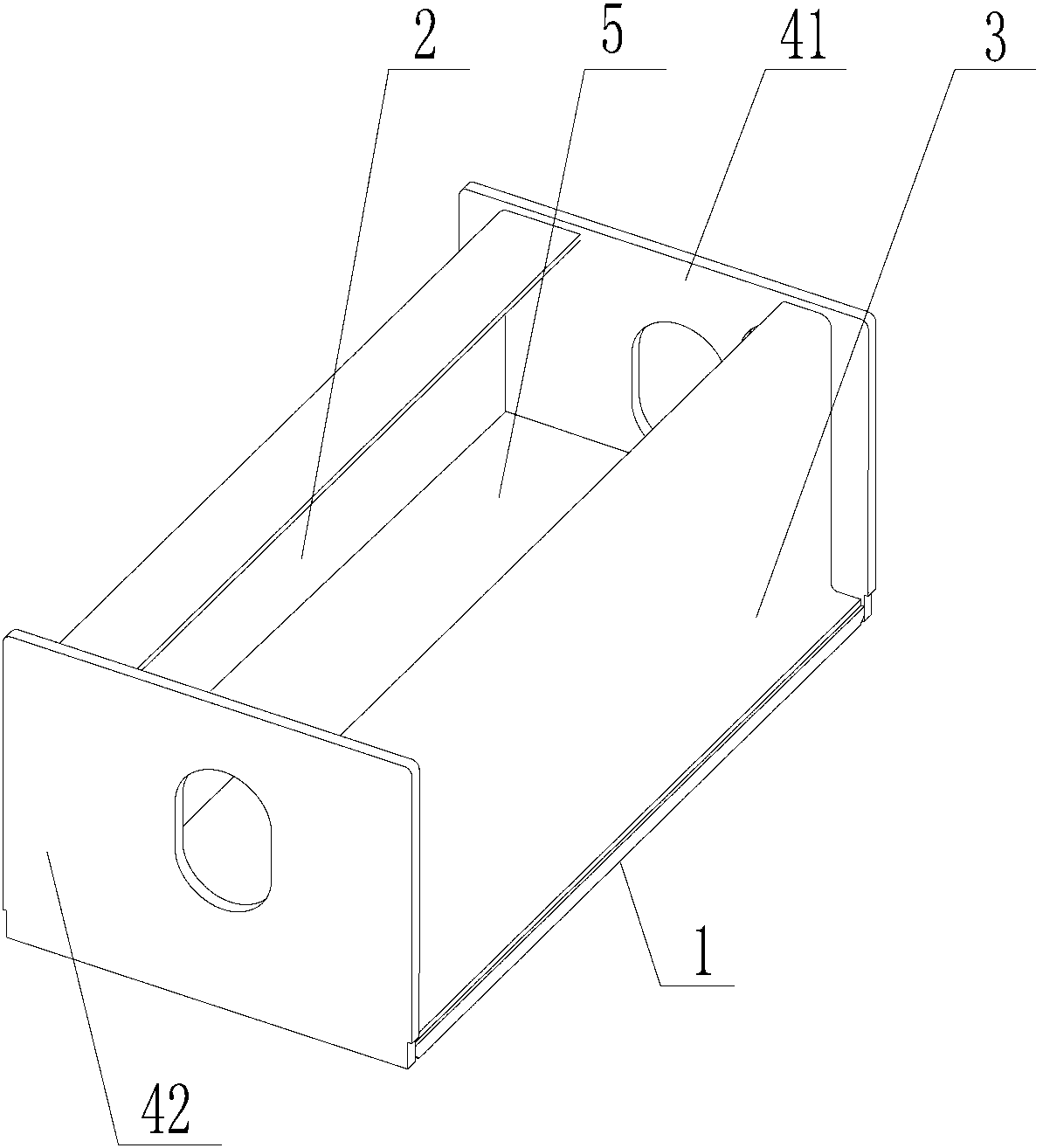
[0063] Above-mentioned 12 embodiments provide the same structure of screed frame, see Figure 3 to Figure 4 , which both include:

[0064] The base plate 1 and the partition plate 5 arranged horizontally, the front plate 2, the rear plate 3, the first side plate 41 and the second side plate 42 arranged vertically, wherein, the base plate 1, the front plate 2, the rear plate 3, the first side The plate 41 and the second side plate 42 form a cuboid structure whose top is not closed;

[0065] The specific specifications of the screed frame provided by the above-mentioned 12 embodiments are listed in Table 1. in FIG. 1:

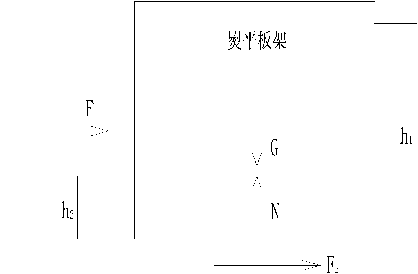
[0066] The height of the screed frame is: the vertical distance between the top surface of the front plate or the rear plate and the bottom surface of the bottom plate;

[0067] The length of the screed frame is: the length of the bottom plate;

[0068] The height of the partition is: the vertical distance from the center line of the partition along the horiz...

Embodiment 13~15

[0072] The above-mentioned 3 embodiments provide the same structure of the screed frame, please refer to for details Figure 5 , which differs from Embodiments 1 to 12 in that: the number of separators is 2.

[0073] The specific specifications of the screed frame provided in Examples 13 to 15 are listed in Table 2. The height of the partition in Table 2 is: the vertical distance from the top surface of the first partition to the bottom surface of the second partition arranged in the vertical direction. The distance from the midpoint of the distance to the bottom surface of the slab.

[0074] Table 2 Specific specifications of the screed frame provided by Examples 13 to 15

[0075]

Embodiment 16~18

[0077] The above-mentioned 3 embodiments provide the same structure of the screed frame, please refer to for details Figure 6 and Figure 7 , and its difference from Embodiments 1 to 12 is that it is provided with two vertical reinforcement plates, and the specific specifications of the screed frame provided by Embodiments 16 to 18 are listed in Table 3:

[0078] Table 3 Specific specifications of the screed frame provided by Examples 16-18

[0079]


PUM


Abstract

The invention discloses a screed plate frame, a screed plate and a paver. The screed plate frame comprises a base plate, a front plate, a rear plate, a first lateral plate, a second lateral plate and a separation plate component arranged horizontally, wherein the separation plate component comprises at least one separation plate, and the separation plate component, the front plate, the rear plate, the first lateral plate, the second lateral plate and the base plate are arranged in a surrounding mode to form a closed space. Compared with the prior art, the screed plate frame is provided with the separation plate component arranged horizontally, the separation plate component is used to adjust the height of a twist centre of the screed plate frame, so that the height of the twist centre of the screed plate frame is close to 120-160 millimeters or within the range, and therefore when the screed plate frame works, outer load toque suffered by the screed plate frame is close to zero, and torsion deformation of the screed plate frame is reduced. The screed plate frame is simple in structure and free of assistance of external equipment to adjust the bottom surface of the screed plate, manufacturing cost is saved, and labor intensity is lowered.

Description

technical field [0001] The invention relates to the field of engineering machinery, in particular to a screed frame, a screed and a paver. Background technique [0002] The screed is one of the important working devices of the paver. It is mainly used for leveling, shaping and pre-compacting mixed paving materials such as asphalt concrete and stabilized soil. The performance of the screed has a major influence on the final pavement quality of the pavement. [0003] The screed can generally be divided into two types according to its combination mode: assembled type and telescopic type. Compared with the telescopic screed, the assembled screed has a higher resistance to deformation, and is suitable for road construction with high surface smoothness such as high-grade highways, and is widely used. [0004] The screed frame of the assembled screed is generally composed of a basic section screed frame and multiple sub-section screed frames with the same structure as the basic s...

Claims


Application Information

Patent Timeline
IPC IPC(8): E01C19/48
Inventor 姚利龙倪东升王友宝
Owner SANY HEAVY IND CO LTD (CN)
Why Eureka
Try Eureka