


Quick Research
Generate reliable direction feasibility study reports for your R&D in just a few steps.

Technical Q&A
Discover and master advanced knowledge NOW. Basics, ideas, possibilities, all at once.

Find Solutions
As an expert in R&D theories, this can generate solutions to your technical problems instantly.

Evaluate Feasibility
Analyze your overall solution with one click, know your potential R&D risks in advance.

Monitor Landscape
Get weekly tech updates, stay abreast of the latest tech innovations and key insights.
Adjusting method for sealing level of magnetic end face seal and special device thereof
A technology of end face sealing and adjustment method, which is applied in the direction of engine sealing, engine components, mechanical equipment, etc., can solve the problems of unadjustable sealing level, and achieve the effects of low cost, wide application range, and convenient adjustment and operation.
- Summary
- Abstract
- Description
- Claims
- Application Information
AI Technical Summary
Problems solved by technology
Method used
Image

Examples
Embodiment 1
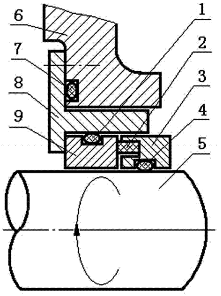
[0074] Embodiment 1, the present invention provides a magnetic end face sealing device, which mainly includes a carbon graphite ring 2, a moving ring 3, a rotating shaft 5, a housing 6, a mounting seat 8, a static ring 9, an adjusting ring 10, and the matching surfaces The mounting seat 8 adopts a cylindrical structure with protruding rings on both sides inside and outside. The mounting seat 8 is fixedly installed on the housing 6. The moving ring 3 and the rotating shaft 5 compress the moving ring auxiliary O-ring 4 into a fixed position. Cooperate with the rotating shaft 5 to rotate, and the static ring 9 fitted in the mounting seat 8 is arranged coaxially with the rotating shaft 5 and contacts with the end surface of the moving ring 3 to form a friction pair; the contact surface of the moving ring 3 and the static ring 9 is provided with carbon Graphite ring 2, carbon graphite ring 2 is embedded in the moving ring body made of magnetically permeable material, the static ring...
Embodiment 2
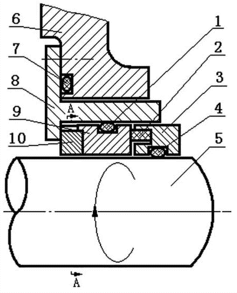
[0090] Embodiment 2, another embodiment of the present invention is: the mounting seat 81 can also adopt a cylindrical straight-through mounting seat 81 with a convex ring and an axial extension on the outside, and a pin hole and a clip are provided at the outer end of the straight-through mounting seat 81 ring groove, and cooperate with the sleeve snap ring 12 in the snap ring groove; set the adjustment ring 10 on the rotating shaft 5, the outside of the adjustment ring 10 is matched with the inside of the snap ring 12 of the mounting seat 81, and the inner side of the adjustment ring 10 is matched with the installation The outer end surface of the seat 81 is matched, the inner end of the mounting seat 81 is matched with the outer end surface of the static ring 9, a groove is arranged on the outer periphery of the adjustment ring 10, and the stop pin 11 is fitted in the pin hole, and the inner end of the stop pin 11 is inserted into the adjustment In the outer peripheral groov...
Embodiment 3
[0094] Embodiment 3, the present invention can also set more than one boss at the position corresponding to the outer peripheral groove of the adjustment ring 10 at the outer end of the static ring 9 , and the bosses on the static ring 9 fit into the outer peripheral groove of the adjustment ring 10 . refer to Figures 1 to 27 , all the other are with above-mentioned embodiment 1 or 2.
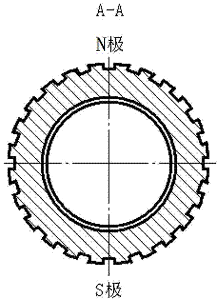
[0095] Through the adjustment ring 10 outer diameter is provided with the groove that determines to install the strong, middle and weak corner positions and cooperates with the center symmetrical multi-groove positioning device of the static ring 9 end face bosses, the center symmetry multi-slot formed by the stop groove and the synchronous end face bosses. The slot positioning device can select the angular position, and at the same time prevent the strong and weak changes of the magnetic force from being affected by the angular misalignment caused by vibration.
PUM
 Abstract
Description
Claims
Application Information
 - R&D Engineer
- R&D Manager
- IP Professional
- Industry Leading Data Capabilities
- Powerful AI technology
- Patent DNA Extraction
Browse by: Latest US Patents, China's latest patents, Technical Efficacy Thesaurus, Application Domain, Technology Topic, Popular Technical Reports.
© 2024 PatSnap. All rights reserved.Legal|Privacy policy|Modern Slavery Act Transparency Statement|Sitemap|About US| Contact US: help@patsnap.com