Foaming mold for manufacturing PU (polyurethane) automobile back cushion

A technology of foaming molds and cushions, which is applied in the field of foaming molds for manufacturing PU automobile cushions. It can solve problems such as affecting quality, poor exhaust effect at the top, and inconvenient product removal, so as to improve safety and reliability and reduce possibilities. Effect

Active Publication Date: 2012-11-28
NANTONG CHAODA EQUIP CO LTD
View PDF4 Cites 5 Cited by
  • Summary
  • Abstract
  • Description
  • Claims
  • Application Information

AI Technical Summary

Problems solved by technology

[0002] When automobile manufacturers produce PU car cushions, the top of the PU car cushion is U-shaped. This structure has certain disadvantages when designing molds: since the top of the product is U-shaped, the first action when opening the mold is The vertical movement of the mold base, the product will follow the upper mold when demoulding, and the product will also move vertically relative to the lower mold. At this time, the undercut part of the lower mold will hold the product, and the product will be easily damaged if it is difficult to demould; At the same time, the exhaust effect on the top of the product on the upper mold is very poor, and the exhaust cylinder cannot be installed, which eventually leads to incomplete foaming of the product and affects the quality; in addition, after the product is opened with the upper mold, it is far away from the operation side, which brings inconvenience to the product. inconvenient

Method used


Image

  • Foaming mold for manufacturing PU (polyurethane) automobile back cushion
  • Foaming mold for manufacturing PU (polyurethane) automobile back cushion
  • Foaming mold for manufacturing PU (polyurethane) automobile back cushion

Examples


Embodiment Construction

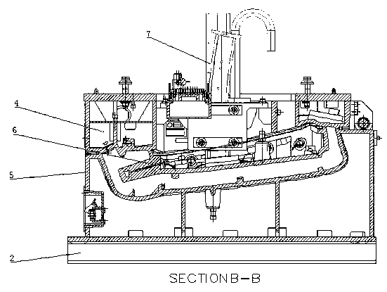
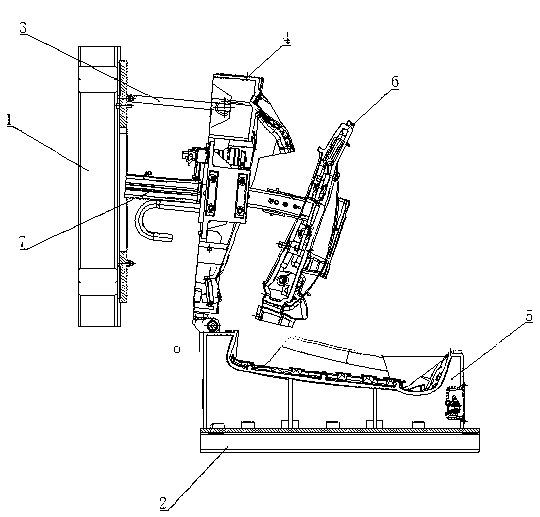
[0016] Such as figure 1 , 2 Shown, comprise upper mold frame 1, lower mold frame 2, mold opening chain 3, upper mold 4, lower mold 5, middle block 6, separation driving mechanism 7, locking cylinder 81, locking shaft 82, detector 83.

[0017] The ends of the above-mentioned upper mold base 1 and lower mold base 2 are hinged (not shown in the figure), the two sides of the lower mold base 2 are equipped with a mold base turning cylinder, and the piston rod of the mold base turning cylinder is connected to the two sides of the upper mold base. Hinged midside. The front ends of the upper mold base 1 and the lower mold base 2 are provided with mechanisms for locking the upper and lower mold bases, and the mold base structures all adopt commonly used known structures, which will not be repeated here.

[0018] Mold comprises upper die 4, lower die 5 and middle block 6, the ends of upper die 4 and lower die 5 are hinged, lower die 5 is fixed on lower die frame 2, middle block 6 is a...


PUM


Abstract

The invention relates to a foaming mold for manufacturing a PU (polyurethane) automobile back cushion, wherein the foaming mold for manufacturing the PU (polyurethane) automobile back cushion comprises an upper mold frame, a lower mold frame and a mold; tail ends of the upper mold frame and the lower mold frame are articulated through an articulated chain; and mold frame turning air cylinders arearranged at two sides of the lower mold frame. The foaming mold for manufacturing the PU (polyurethane) automobile back cushion is characterized in that the mold comprises an upper mold, a lower moldand an intermediate mold; tail ends of the upper mold and the lower mold are articulated; the lower mold is fixed on the lower mold frame; the intermediate block is arranged between the upper mold and the lower mold; a separating driving mechanism for driving the intermediate block is installed on the upper mold; and a mold opening chain is arranged between the back surface of the upper mold and the upper mold frame. The upper mold and the lower mold are connected through an articulated chain, the product acts along with the upper mold and the intermediate block together, the product moves rotatably permanently relative to the lower mold, and at the same time, the possibility for pulling the product to be damaged by the lower mold is reduced greatly; and additionally, when the mold is opened and the product is removed, the product and the intermediate block are projected out together, and the foamed product is more convenient to be taken down by the operation personnel.

Description

technical field [0001] The invention relates to a foaming mold, in particular to a foaming mold for making PU automobile cushions. Background technique [0002] When automobile manufacturers produce PU car cushions, the top of the PU car cushion is U-shaped. This structure has certain disadvantages when designing molds: since the top of the product is U-shaped, the first action when opening the mold is The vertical movement of the mold base, the product will follow the upper mold when demoulding, and the product will also move vertically relative to the lower mold. At this time, the undercut part of the lower mold will hold the product, and the product will be easily damaged if it is difficult to demould; At the same time, the exhaust effect on the top of the product on the upper mold is very poor, and the exhaust cylinder cannot be installed, which eventually leads to incomplete foaming of the product and affects the quality; in addition, after the product is opened with th...

Claims


Application Information

Patent Timeline
Patent Type & Authority Applications(China)
IPC IPC(8): B29C44/58B29L31/58
Inventor 冯建军
Owner NANTONG CHAODA EQUIP CO LTD
Why Eureka
Try Eureka