artificial knee joint

A technology for artificial knee joints and knee joints, applied in the direction of knee joints, elbow joints, joint implants, etc., can solve the problem that it is difficult to meet the special needs of oriental races, the knee joint has a large degree of flexion, and cannot well adapt to the needs of domestic patients and other problems, to achieve the effect of reducing the deformation of the joint pad, reducing the stress, and combining tightly

Inactive Publication Date: 2015-11-18
RESEARCH INSTITUTE OF TSINGHUA UNIVERSITY IN SHENZHEN
View PDF6 Cites 0 Cited by
  • Summary
  • Abstract
  • Description
  • Claims
  • Application Information

AI Technical Summary

Problems solved by technology

[0004] The anatomy of the knee joint and the geometric characteristics of the articular surface are the basis for the design of the artificial knee joint. However, most of the artificial knee joint products currently in clinical use are the products of Depuy, Zimmer, Smith&Nephew, and Stryker, which are based on the knee joint anatomy of Western races. The serialized and standardized design of prostheses based on the anatomy and articular surface geometric characteristics is biased towards the anatomical characteristics and living habits of Westerners, and it is difficult to meet the special needs of Eastern races and other Eastern races.
For example, the tibial plateau osteotomy area of ​​Orientals is smaller than that of Westerners, and the ratio of transverse diameter to anterior-posterior diameter of tibial plateau is greater than that of Westerners, which is more obvious in short oriental women; Differences in daily behavior, sports and culture lead to greater knee flexion in Eastern races than in Westerners; the medical community generally reflects that existing American and European artificial joint products cannot well meet the needs of domestic patients

Method used


Image

  • artificial knee joint
  • artificial knee joint
  • artificial knee joint

Examples


Embodiment Construction

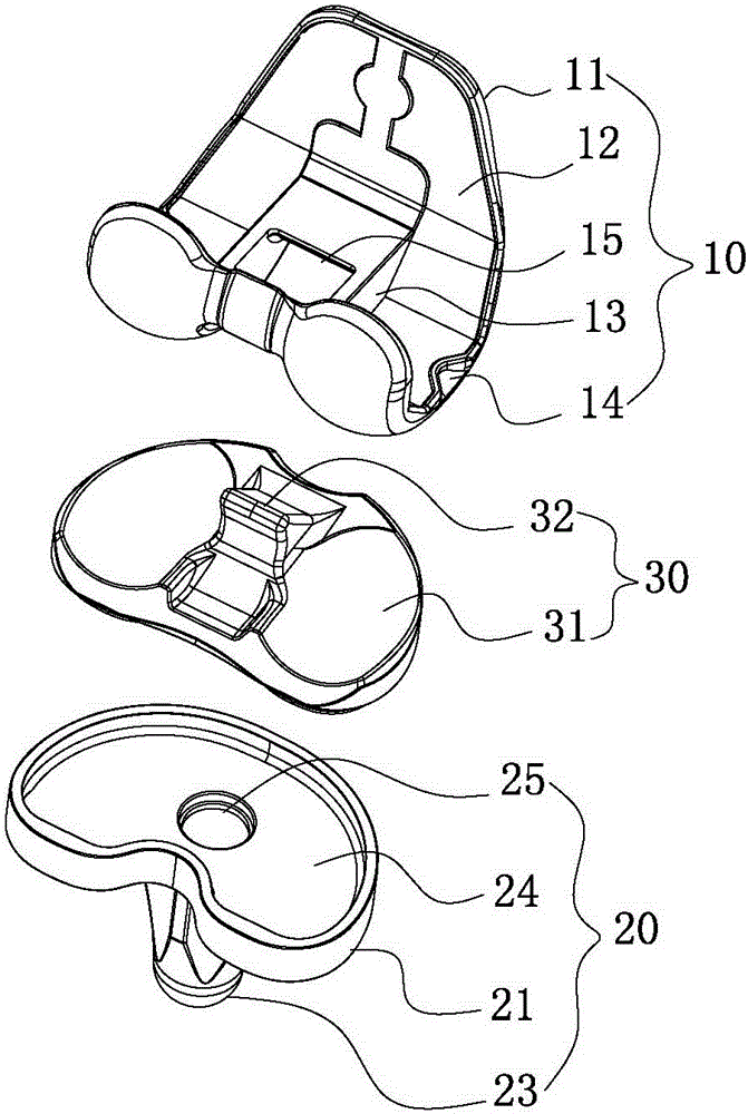
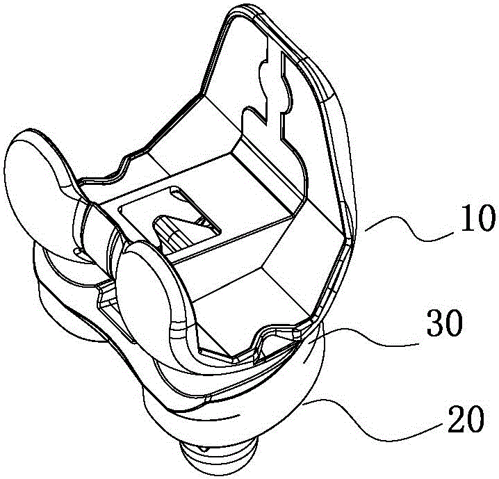
[0027] Such as Figure 1-8 As shown, a kind of artificial knee joint of the present invention includes femoral condyle prosthesis 10, tibial plateau prosthesis 20, joint liner 30,

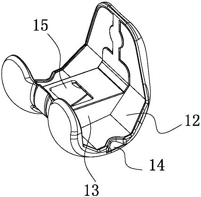
[0028] Femoral condyle prosthesis 10 comprises femoral articular surface 11, condyle joint surface 12, intercondylar joint surface 13, positioning wing 14, square hole 15, femoral articular surface 11 is positioned at the back both sides of femoral condyle prosthesis 10, femoral condyle prosthesis The front of 10 is a platform, has square hole 15 on the platform, and the two sides of platform are intercondyle junction surface 13, and the both sides of platform are condyle junction surface 12, have positioning wing 14 on the side of condyle junction surface 12;

[0029] The femoral articular surface 11 is a highly polished curved surface to reduce the coefficient of friction with the joint liner 30. The shape and size of the femoral articular surface 11 match the anatomical characteristics of the or...


PUM


Abstract

The invention relates to an artificial knee joint. The artificial knee joint comprises a femoral condyle prosthesis, a tibial platform prosthesis and a joint gasket, wherein the femoral condyle prosthesis is movably placed on the tibial joint surface of the joint gasket through the femoral joint surface after being assembled; a projection in the middle of the joint gasket extends into a square hole in the middle of the femoral condyle prosthesis to limit the motion range of the knee joint and prevent the dislocation of the joint; a protrusion part of the joint gasket is movably mounted on a profiled groove of the femoral condyle prosthesis; and a gibbosity part of the joint gasket is movably mounted on a middle circular groove of the tibial platform prosthesis. Due to the adoption of the structure, the technical problem of mismatching of anatomic forms of the conventional artificial knee joint product and the oriental knee joint due to different anatomic forms of the oriental knee joint and the occidental knee joint is solved. The artificial knee joint is suitable for the orientals or the oriental patients requiring total knee arthroplasty.

Description

technical field [0001] The invention relates to an artificial joint replacement device, in particular to an artificial knee joint. Background technique [0002] Artificial joint replacement has been widely promoted in China, and has been widely used in the treatment of shoulder joints, elbow joints, wrist joints, interphalangeal joints, hip joints, knee joints and ankle joints, among which the marrow joint and knee joint are the most common . Several major foreign manufacturers occupy more than 60% of the total artificial joint market, such as Depuy, Zimmer, Smith&Nephew, Stryker and other brand products are the most frequently used products by doctors in joint replacement surgery. Domestic artificial joint products are mostly imitated with reference to the technical parameters of imported joint products. Although they also occupy a certain market share, many doctors are not inclined to choose them due to the technology and lack of R&D investment. [0003] The knee joint i...

Claims


Application Information

Patent Timeline
Patent Type & Authority Patents(China)
IPC IPC(8): A61F2/38
CPCA61F2/38A61F2002/30001
Inventor 尚鹏白雪岭卢俊哲
Owner RESEARCH INSTITUTE OF TSINGHUA UNIVERSITY IN SHENZHEN
Why Eureka
Try Eureka