
Hollow spindle with spiral guide grooves

A hollow spindle and guide groove technology is applied in the field of hollow spindles and hollow spindles in twisting devices, which can solve the problems of not considering the law of action, increasing friction, uneven yarn evenness, etc., so as to improve the ability of cohesion and entanglement. The effect of changing the relative position and improving the yarn strength

Active Publication Date: 2014-11-26
SHAOXING UNIVERSITY
View PDF10 Cites 4 Cited by
  • Summary
  • Abstract
  • Description
  • Claims
  • Application Information

AI Technical Summary

Problems solved by technology

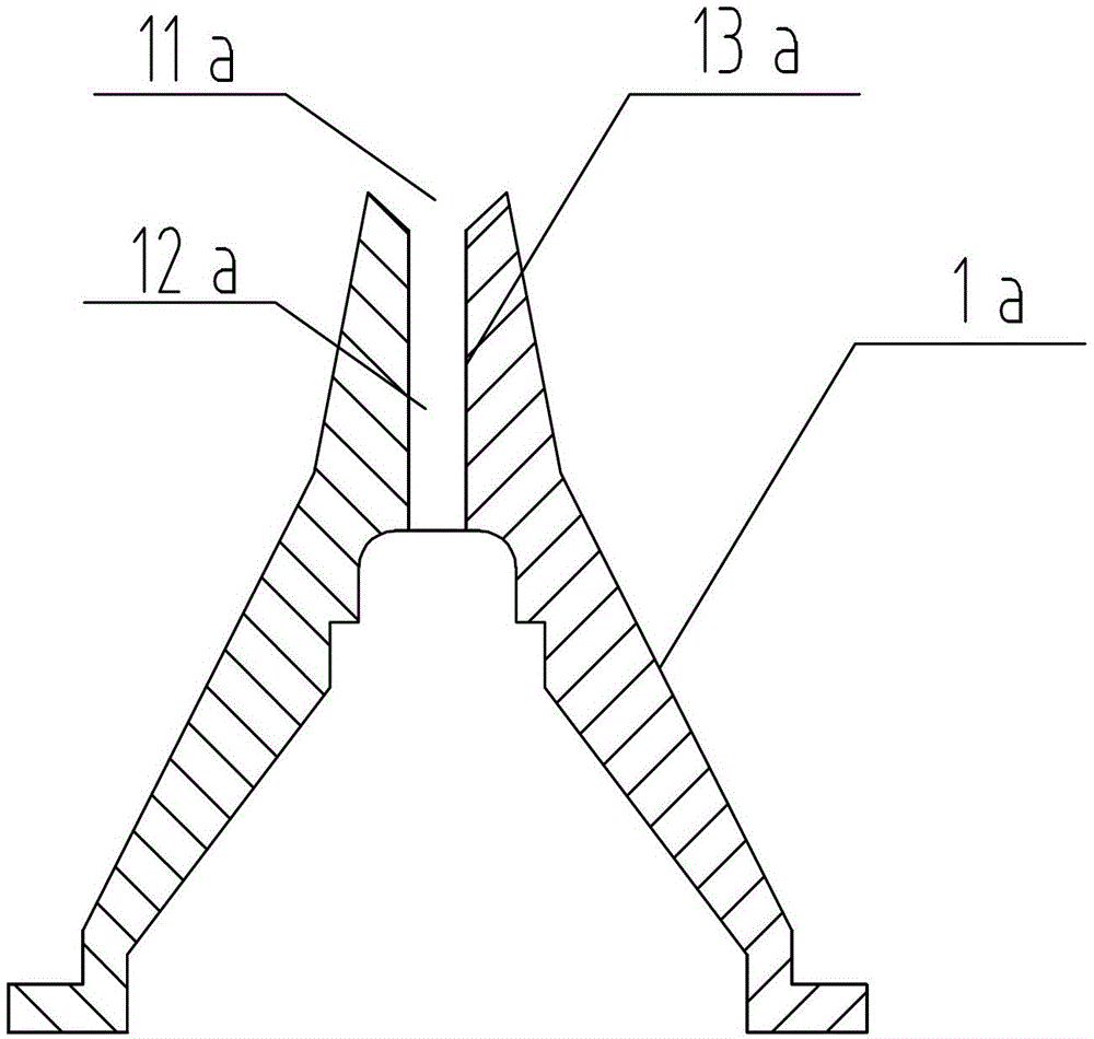
The entrance surface groove 13a helps to increase the friction between the free-end fiber and the entrance of the hollow spindle 1a, so that the fiber itself rotates to a certain extent while rotating around the hollow spindle 1a, resulting in a tight yarn structure and improved yarn strength. It must be improved; but this invention does not consider the law of interaction between the rotating airflow of the twisting chamber and the outer surface of the hollow spindle, nor does it consider the actual situation that the free tail end of the fiber in the twisting chamber lies on the outer surface of the hollow spindle inlet, and the fiber winds around the hollow spindle 1a The effect of self-rotation while rotating is not obvious, the yarn structure is loose, the strength is not high, and the yarn evenness is uneven

Method used

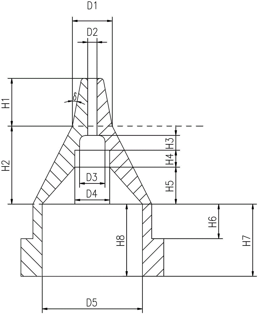

Image

  • Hollow spindle with spiral guide grooves
  • Hollow spindle with spiral guide grooves
  • Hollow spindle with spiral guide grooves

Examples


Embodiment 1

[0030] figure 2 , 3 4. A hollow spindle with a spiral guide groove in the present invention is divided into an upper part 1A, a middle part 1B and a lower part 1C, and the height of the upper part 1A is H 1 5.8mm, the half cone angle of the upper part 1A δ The upper part 1A is provided with a fiber inlet 11 and a yarn guide channel 12, and the outer surfaces of the upper part 1A and the middle part 1B are uniformly provided with 6 guide grooves 13, and the fiber inlet 11 is a smooth structure after chamfering, and the bottom of the upper part 1A diameter D 1 4.8mm, yarn guide channel 12 diameter D 2 is 1.0mm; the middle part 1B is provided with a small inner hole 14, a large inner hole 15 and a cavity 16, and the height of the middle part 1B is H 2 9.2mm, small inner hole 14 diameter D 3 3mm, small inner hole 14 height H 3 2mm, large inner hole 15 diameter D 4 4mm, large inner hole 15 height H 4 2mm, conical cavity 16 height H 5 4.5mm; the lower part 1C is a "convex...

Embodiment 2

[0034] The principle and other settings of this embodiment are the same as those of Embodiment 1, the difference being:

[0035] Upper 1A Height H 1 6.4mm, the half cone angle of the upper part 1A δ is 10°, the number of guide grooves 13 is 6, and the diameter of the bottom end of the upper part 1A is D 1 5.5mm, yarn guide channel 12 diameter D 2 1.2mm; middle part 1B height H 2 10.2mm, small inner hole 14 diameter D 3 3.6mm, small inner hole 14 height H 3 2.4mm, large inner hole 15 diameter D 4 4.8mm, large inner hole 15 height H4 2.6mm, tapered cavity 16 height H 5 4.8mm; hollow spindle outlet 17 inner diameter D 5 10.2mm, the distance H between the bottom of the middle part 1B and the convex surface of the lower part 1C 6 3.6mm, lower part 1C height H 7 7.2mm, hollow spindle outlet height H 8 7.2 mm; the helix angle through which the centerline of the guide groove 13 turns θ is 90°, the groove width L of the guide groove 13 is 0.1~8mm, and the groove depth h of...

Embodiment 3

[0038] The principle and other settings of this embodiment are the same as those of Embodiment 1, the difference being:

[0039] There are 3 guide grooves 13, and the diameter of the bottom end of the upper part 1A is D 1 6.8mm, the diameter D of the yarn guide channel 12 2 1.4mm, small inner hole 14 diameter D 3 4.2mm, large inner hole 15 diameter D 4 5.6mm, hollow spindle outlet 17 inner diameter D 5 12mm, height H of upper part 1A 1 6.8mm, the half cone angle of the upper part 1A δ 12°, height H of middle part 1B 2 11.4mm, small inner hole 14 height H 3 2.2mm, large inner hole 14 height H 4 2.8mm, tapered cavity 16 height H 5 The distance H between the bottom of the middle part 1B and the convex surface of the lower part 1C is 5.2mm 6 4.3mm, lower part 1C height H 7 9 mm, hollow spindle outlet height H 8 8.6 mm; the helix angle that the center line of the guide groove 13 turns θ is 120°, the groove width L of the guide groove 13 is 0.1-10 mm, and the groove de...


PUM

PropertyMeasurementUnit
depthaaaaaaaaaa
angleaaaaaaaaaa
diameteraaaaaaaaaa

Abstract

The invention discloses a hollow spindle with spiral guide grooves and belongs to the technical field of a hollow spindle of a twisting device. The hollow spindle is divided into an upper part, a middle part and a lower part, wherein the outer surface extending from a fiber inlet at the upper part to the bottom end at the middle part is provided with three to twelve guide grooves, the guide grooves are in a spiral shape, the groove depth of the guide grooves is 0 to 1.2mm, the groove width of the guide grooves is 0.05 to 12mm, the rotating spiral angle of the center line of the guide grooves is 30 to 120 degrees, the fiber inlet is in a structure subjected to chamfering smoothening treatment, the height of the upper part of the hollow spindle is 5 to 8mm, the hemipyramid angle of the upper part is 5 degrees to 15 degrees, the diameter of a yarn guide passage is 0.8 to 1.4mm, the height of the middle part is 8 to 12mm, the height of the lower part is 5 to 9mm, and the inner diameter of an outlet of the hollow spindle is 9 to 14mm. The hollow spindle has the advantages that the yarning forming is compact, the yarn levelness uniformity is good, the yarn strength is improved, and the hollow spindle adapts to beyber yarns and colored spun yarns of air jet vortex spinning.

Description

technical field [0001] The invention relates to a hollow spindle with a spiral guide groove, which belongs to the technical field of hollow spindles in twisting devices. Background technique [0002] Air-jet vortex spinning integrates roving, spun yarn, winding and winding, overcomes the shortcomings of large rotational inertia of parts and low twisting efficiency in the traditional twisting process, and uses high-speed rotating air to twist free-end fibers into yarn, spinning The speed is up to 450m / min; the yarn produced has a double structure, consisting of core fiber and outer wrapping fiber, which has the appearance of ring spinning, but the outer wrapping spiral fiber is not as tightly wrapped as mechanically controlled, and the yarn strength is not as good as ring spinning The spinning yarn has high tenacity. [0003] The way to improve yarn strength of air-jet vortex spinning is not only to optimize the yarn-forming process parameters, but also to design the shape a...

Claims


Application Information

Patent Timeline
Patent Type & Authority Patents(China)
IPC IPC(8): D01H7/88D01H4/02
CPCD01H1/115
Inventor 邹专勇
Owner SHAOXING UNIVERSITY
Learn More