
End part sealing method of sintering machine

An end sealing and sintering machine technology, applied in the field of sintering machine sealing, can solve the problems of sealing surface wear of the sealing device, large air leakage at the end of the sintering machine, air leakage at the end of the sintering machine, etc., so as to reduce the air volume and improve the fit. effect, the effect of improving the service life and the reliability of the work

Active Publication Date: 2014-12-10
SHANDONG PROVINCE METALLURGICAL ENG CO LTD
View PDF6 Cites 0 Cited by
  • Summary
  • Abstract
  • Description
  • Claims
  • Application Information

AI Technical Summary

Problems solved by technology

[0003] 1. The bonding effect between its sealing surface and the bottom of the trolley is poor, which is the main reason for the large air leakage at the end of the sintering machine
[0004] 2. Its sealing surface slides relative to the bottom of the trolley. Due to the large number of trolleys, the sealing surface of the sealing device is severely worn; at the same time, the vulnerable part is not easy to replace and repair, which also causes air leakage at the end of the sintering machine one of the reasons

Method used


Image

  • End part sealing method of sintering machine

Examples


Embodiment 1

[0021] Example 1, such as figure 1 shown.

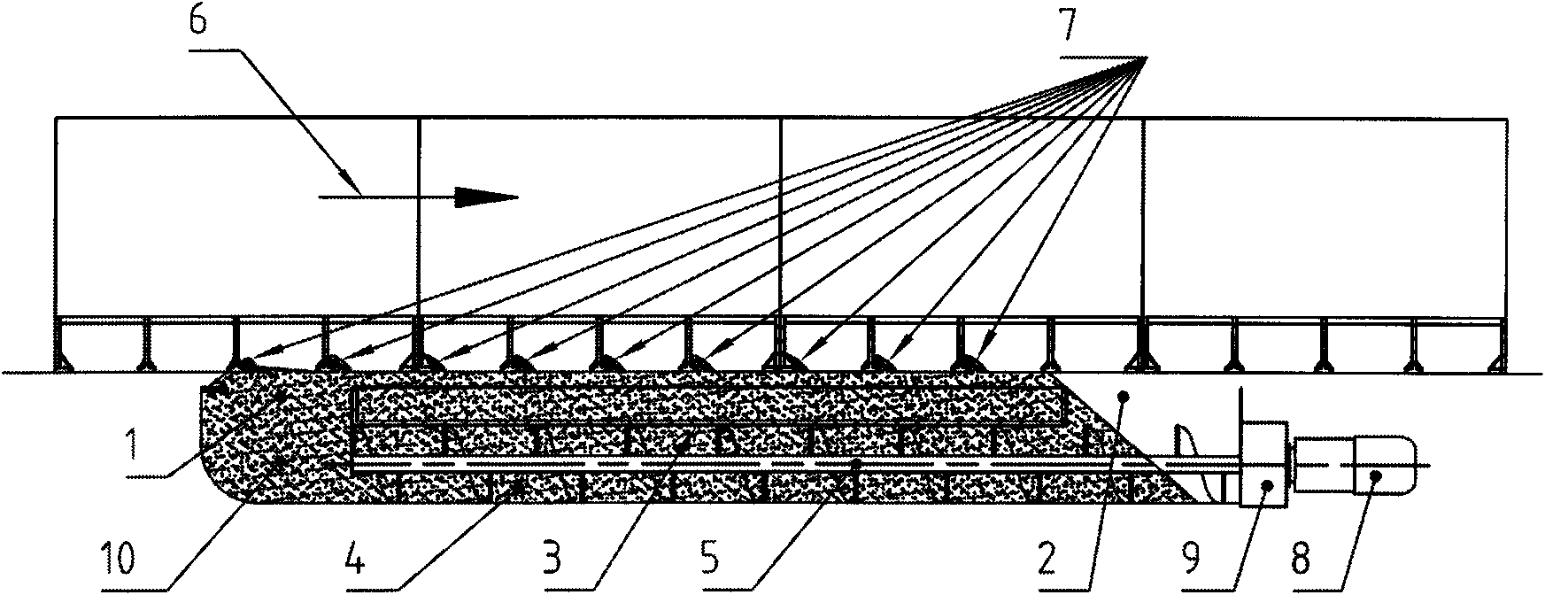
[0022] exist figure 1 Among them, 1 is the sand outlet provided at the front end of the end sealing device, the sand outlet 1 can be independent, or it can be implied in the outlet of the sand conveying device, such as a screw conveyor, in other words In other words, the sand outlet 1 can be integrated with the outlet of the sand conveying device, such as a screw conveyor. 2 is the falling sand tank provided at the rear end of the end sealing device. 3 is a sand table arranged between the sand outlet and the sand falling tank. 4 is a sand returning channel arranged between the sand outlet and the sand falling tank. 5 is the conveying device of sand, specifically, what it has adopted is a screw conveyor. It should be noted that the sand return passage 4 and the conveying device 5 of sand (specifically, it adopts a screw conveyor) are combined into one. Arrow 6 represents the forward direction of the sintering trolley. 7 represe...


PUM


Abstract

The invention provides an end part sealing method of a sintering machine, and belongs to the technical field of sintering machine sealing. The end part sealing method comprises the use of an end part sealing device, and is characterized in that a sand outlet is formed at the front end of the end part sealing device; a sand dropping groove is formed at the back end of the end part sealing device; a sand table and a sand return channel are arranged between the sand outlet and the sand dropping groove; a sand conveying device is arranged, so as to enable the sand dropped into the sand dropping groove to return to the sand outlet of the sand table through the sand return channel and gush out upwards from the sand outlet; and meanwhile, the adoption of metal sand is recommended, so as to enhance the wind blocking ability of the end part sealing device. The end part sealing method suitable for end part sealing of the sintering machine has the advantages that the attaching effect of a sealing surface of the end part sealing surface, namely the upper surface of the sand and the bottom of a trolley can be effectively improved, air leakage of the sintering machine is reduced, the air quantity of a main air exhaust blower is decreased, the aim of energy conservation is achieved, the service life of the end part sealing device is prolonged, and the reliability, the maintainability of the end part sealing device are improved.

Description

technical field [0001] The invention relates to an end sealing method of a sintering machine, belonging to the technical field of sintering machine sealing. Background technique [0002] Sintering machine is a kind of equipment widely used in metallurgical enterprises. The air leakage rate of the sintering machine is generally as high as 50%, or even higher; among them, the air leakage at the end accounts for more than half of the total air leakage. The disadvantages of the end sealing device of the existing sintering machine are: [0003] 1. The bonding effect between its sealing surface and the bottom of the trolley is poor, which is the main reason for the large air leakage at the end of the sintering machine. [0004] 2. Its sealing surface slides relative to the bottom of the trolley. Due to the large number of trolleys, the sealing surface of the sealing device is severely worn; at the same time, the vulnerable part is not easy to replace and repair, which also cause...

Claims


Application Information

Patent Timeline
Patent Type & Authority Patents(China)
IPC IPC(8): F27B21/08
Inventor 姚朝胜
Owner SHANDONG PROVINCE METALLURGICAL ENG CO LTD
Learn More