
Vacuum servo safety control system and control method for new energy vehicle

A new energy vehicle, vacuum boosting technology, applied in the direction of braking safety system, can solve problems such as insufficient vacuum pressure and reduce braking safety, and achieve the effect of improving vehicle safety and reducing the incidence of driving accidents.

Active Publication Date: 2014-08-20
益阳仪纬科技有限公司
View PDF4 Cites 0 Cited by
  • Summary
  • Abstract
  • Description
  • Claims
  • Application Information

AI Technical Summary

Problems solved by technology

For conventional new energy vehicles, when the whole vehicle is in a stopped state, after the start key is pulled out, the vehicle controller and vacuum pressure sensor will not work with a delay, and will not detect the vacuum degree in the vacuum tank; when the driver starts the vehicle next time When braking is needed instantaneously, the vacuum pressure is often insufficient, which reduces the safety of braking

Method used


Image

  • Vacuum servo safety control system and control method for new energy vehicle
  • Vacuum servo safety control system and control method for new energy vehicle
  • Vacuum servo safety control system and control method for new energy vehicle

Examples


Embodiment Construction

[0020] In order to make the object, technical solution and advantages of the present invention clearer, the present invention will be described in further detail below in conjunction with specific embodiments and with reference to the accompanying drawings.

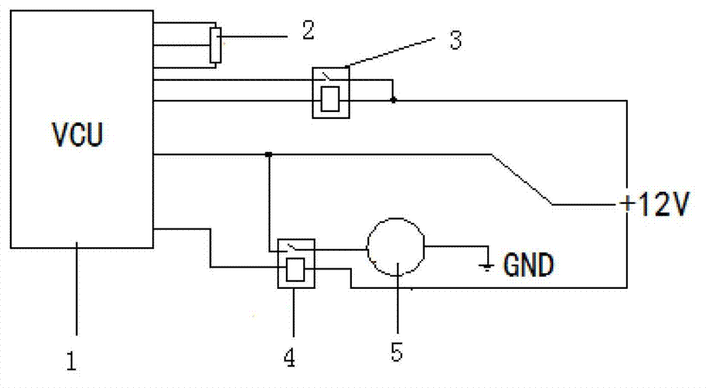
[0021] figure 1 It is a schematic circuit diagram of a vacuum booster safety control system for a new energy vehicle according to an embodiment of the present invention. Such as figure 1 As shown, the new energy vehicle vacuum booster safety control system includes a vehicle controller 1 (Vehicle Control Unit, VCU), an electric vacuum pump 5 , a vacuum pressure sensor 2 and a first relay 3 and a second relay 4 . The coil of the first relay 3 is connected in series between the 12V battery and the vehicle controller 1 , and the normally open contact corresponding to the coil of the first relay 3 is connected between the 12V battery and the vehicle controller 1 . The coil of the second relay 4 is connected in series betwee...


PUM


Abstract

The invention discloses a vacuum servo safety control system for a new energy vehicle, which comprises a whole vehicle control unit (VCU), an electric vacuum pump, a vacuum pressure sensor and a vacuum container, and further comprises a first relay and a second relay, wherein the coil of the first relay is connected in series between a storage battery and the whole vehicle control unit; a normally open contact corresponding to the coil of the first relay is connected between the storage battery and the whole vehicle control unit; the coil of the second relay is connected in series between the storage battery and the whole vehicle control unit; and a normally open contact corresponding to the coil of the second relay is connected between the whole vehicle control unit and the electric vacuum pump. Practices show that vacuum detection of a stopped vehicle and vacuum re-detection of a started vehicle can be realized, and a driver is prevented from driving a vehicle when vacuum leaks, so as to ensure vacuum brake power assisting requirements of the driver at any time, improve brake reliability, reduce fatigue of the driver, provide convenience for reducing the incidence of driving accidents, and improve the safety of the whole vehicle.

Description

technical field [0001] The invention relates to a vehicle brake boosting control technology, in particular to a vacuum boosting safety control method for a new energy vehicle. Background technique [0002] New energy vehicles mainly include hybrid vehicles, pure electric vehicles and fuel cell vehicles. In order to generate a vacuum source for brake boosting, a set of electric vacuum boosting device must be installed on the new energy vehicle, which pumps air through an electric vacuum pump to achieve the purpose of vacuum boosting. For conventional new energy vehicles, when the whole vehicle is in a stopped state, after the start key is pulled out, the vehicle controller and vacuum pressure sensor will not work with a delay, and will not detect the vacuum degree in the vacuum tank; when the driver starts the vehicle next time When braking is needed instantaneously, the vacuum pressure is often insufficient, which reduces the safety of braking. Contents of the invention ...

Claims


Application Information

Patent Timeline
Patent Type & Authority Patents(China)
IPC IPC(8): B60T17/22
Inventor 张裕强石良根
Owner 益阳仪纬科技有限公司
Learn More