
Pneumatic tire

A pneumatic tire, tire circumferential technology, applied to tire parts, tire tread/tread pattern, transportation and packaging, etc., to achieve the effect of improving tire noise performance, improving tire driving stability, and reducing air pump noise

Inactive Publication Date: 2012-10-31
YOKOHAMA RUBBER CO LTD
View PDF8 Cites 9 Cited by
  • Summary
  • Abstract
  • Description
  • Claims
  • Application Information

AI Technical Summary

Problems solved by technology

Contents of the invention

Method used


Image

  • Pneumatic tire
  • Pneumatic tire
  • Pneumatic tire

Examples


example

[0091] Figure 5 and Figure 6 It is a table showing the performance test results of the pneumatic tire of the present invention. Figure 7 It is a plan view showing a tread of a conventional example pneumatic tire.

[0092] In this performance test, the (1) driving stability performance, (2) noise performance, and (3) wet performance of a plurality of different pneumatic tires were evaluated (see Figure 5 and Figure 6 ). In these performance tests, a pneumatic tire having a tire size of 205 / 55R16 91V was assembled to a rim having a rim size of 16×6.5JJ, and an air pressure of 200 [kPa] was applied to the pneumatic tire. In addition, the test vehicle is an FF (Front engine Front drive, front engine front drive) vehicle with a displacement of 1.4 [L], that is, a passenger car.

[0093] (1) In the relevant performance test of driving stability, the test vehicle is driven on a dry test track, and the test driver performs sensory evaluation on lane changing performance and ...


PUM


Abstract

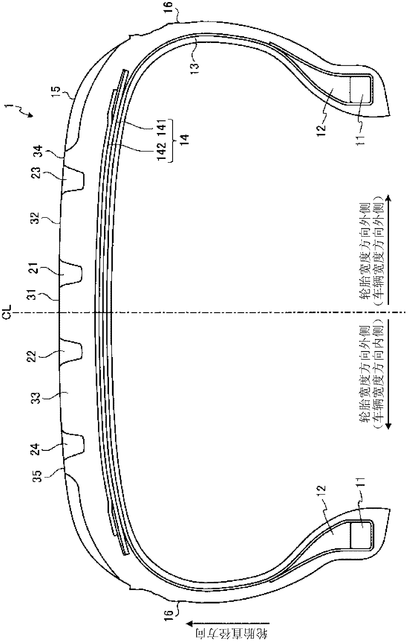
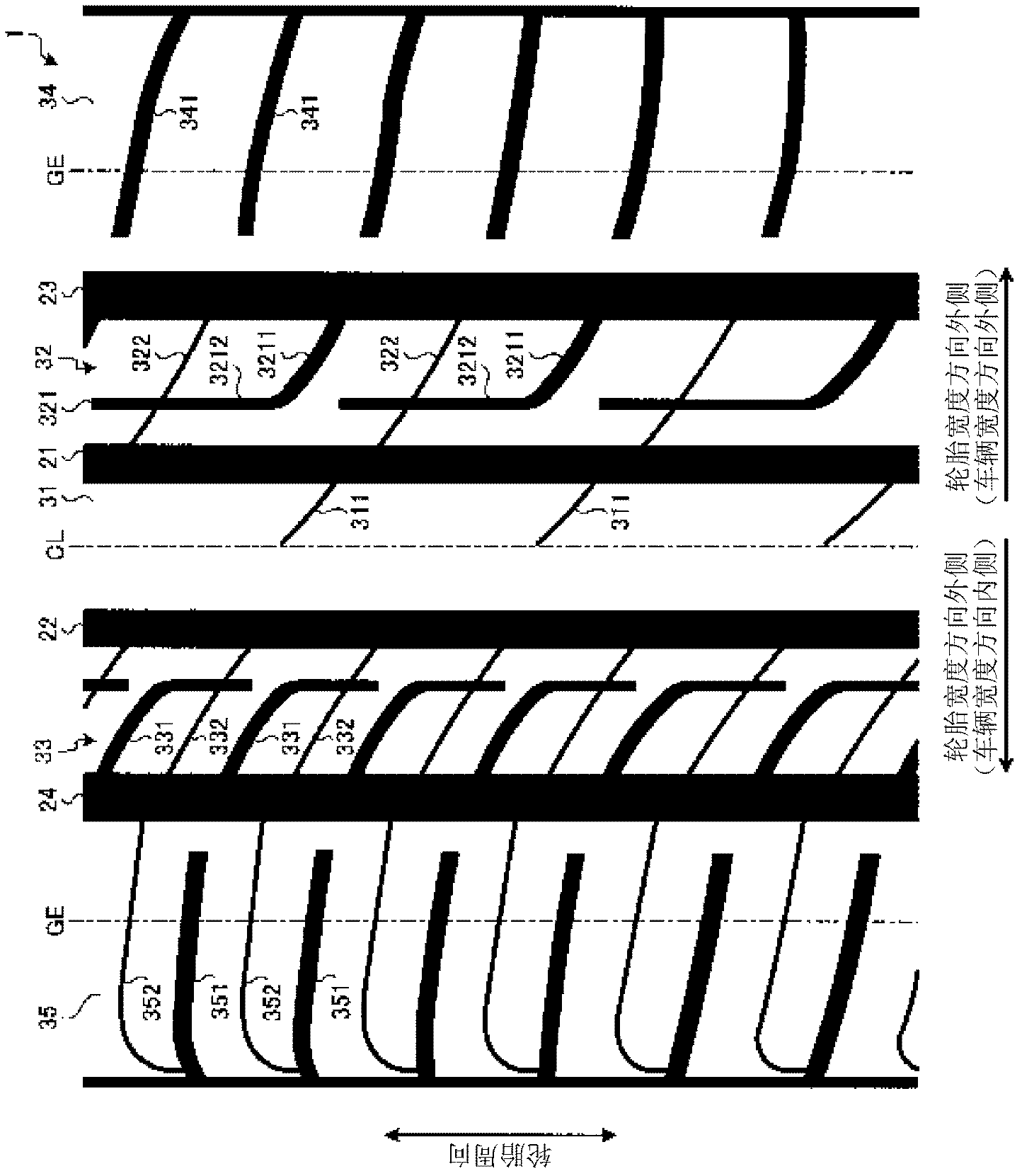
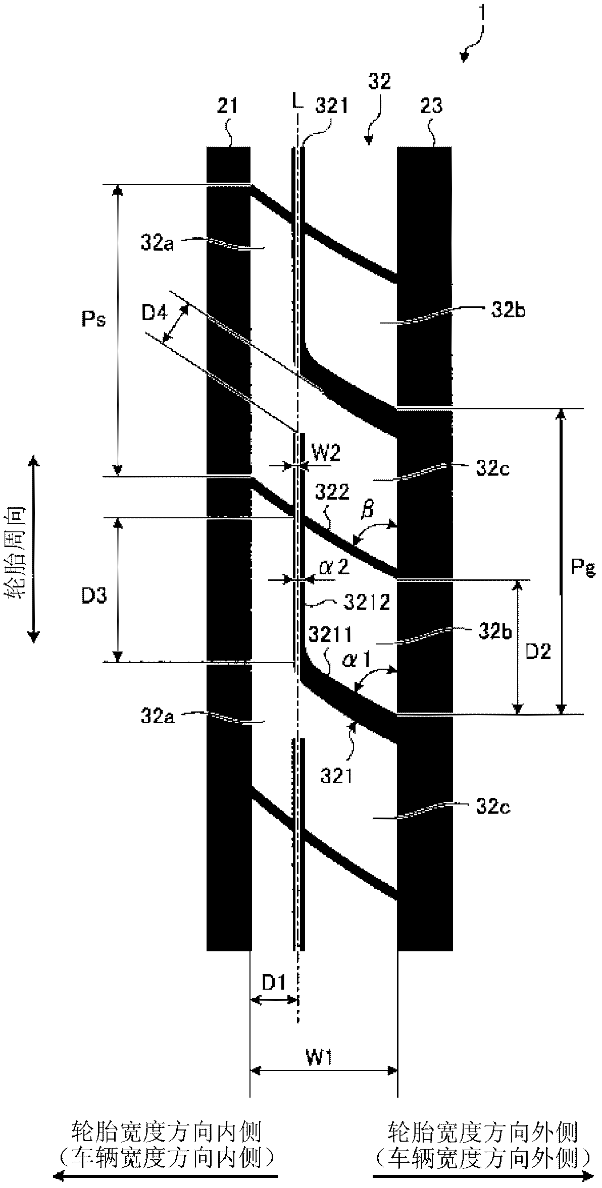
A pneumatic tire including at least four circumferential main grooves extending in the tire circumferential direction and a plurality of rib-like land portions partitioned by the circumferential main grooves in the tread portion. An outer side second land portion includes an L-shaped narrow groove formed by connecting a width direction groove portion extending from an edge portion on an outer side in the tire width direction of the outer side second land portion toward an inner side in the tire width direction, and a circumferential direction groove portion extending substantially parallel to the tire circumferential direction and terminating in an interior portion of the outer side second land portion,and a penetrating sipe penetrating the outer side second land portion in the tire width direction and intersecting the circumferential direction groove portion.

Description

technical field [0001] The present invention relates to a pneumatic tire, and more particularly, to a pneumatic tire capable of improving driving stability and noise performance. Background technique [0002] In recent years, demands regarding driving stability performance and noise performance have been increasing in pneumatic tires. As a conventional pneumatic tire related to this problem, the technique described in Patent Document 1 is known. [0003] prior art literature [0004] patent documents [0005] [Patent Document 1] Japanese Patent No. 4156018 Contents of the invention [0006] The problem to be solved by the invention [0007] An object of the present invention is to provide a pneumatic tire capable of improving tire steering stability and noise performance. Contents of the invention [0008] In order to achieve the above object, the pneumatic tire of the present invention has at least four circumferential main grooves extending in the tire circumferen...

Claims


Application Information

Patent Timeline
IPC IPC(8): B60C11/03
CPCB60C11/1236B60C2011/0381B60C11/0306B60C2011/0388B60C11/0304B60C11/04B60C2011/0341B60C2011/0395B60C2011/039B60C19/002Y10S152/03
Inventor 石田昌宏
Owner YOKOHAMA RUBBER CO LTD
Learn More