
Patsnap Eureka
For R&D, Patsnap Eureka makes reading and utilizing patents & technical documents easy.
Patsnap Eureka AIR
Designed for self-driven R&D workflows. Generate viable solutions, solve complex R&D challenges, empower your innovation with AI.

Patsnap Eureka Materials
Designed for material experts only. Revolutionize your material R&D, from search, analyze, to developing new materials.

TechResearch
Generate reliable direction feasibility study reports for your R&D in just a few steps.

TechSeek
Discover and master advanced knowledge NOW. Basics, ideas, possibilities, all at once.

TechMind
As an expert in R&D Theories, TechMind can generates customized viable solutions instantly.

TechRisk
Analyze your overall solution with one click, know your potential R&D risks in advance.

TechMonitor
Get weekly tech updates, stay abreast of the latest tech innovations and key insights.
Permanent magnetic coil driving circuit
A coil drive and drive circuit technology, applied in electrical components, electronic switches, pulse technology, etc., can solve the problems of multi-port resources, occupation, H-bridge burnout, etc., and achieve the effects of saving port resources, preventing overload, and avoiding burnout
- Summary
- Abstract
- Description
- Claims
- Application Information
AI Technical Summary
Problems solved by technology
Method used
Image

Examples
Embodiment 1
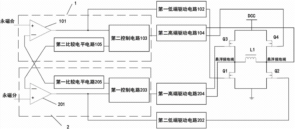
[0044] See figure 1 , 2 , a permanent magnet coil drive circuit, comprising: an H-bridge composed of a first low-end switch tube Q1, a second low-end switch tube Q2, a first high-side switch tube Q3, and a second high-side switch tube Q4, wherein the first A low-side switch tube Q1 and a second high-end switch tube Q4 are paired tubes for the first group of control coils L1 to be energized, and the second low-side switch tube Q2 and the first high-side switch tube Q3 are for the second group to control the coil L1. Electric pair tubes, each high-end switch tube is connected to the corresponding high-end drive circuit, and each low-end switch tube is connected to the corresponding low-end drive circuit;
[0045] It also includes: respectively controlling the first and second groups of tube control circuits with the same structure; the first pair of tube control circuits 1 and the second group of tube control circuits 2 both include : Comparator, control circuit, comparison le...
Embodiment 2
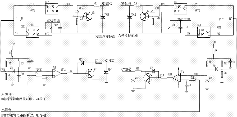
[0069] See image 3 , image 3The specific circuit implementation and principle of the switch tube drive circuit are shown; for the sake of simplicity, the same or similar components use the same or similar labels; in this implementation, the comparator uses a dual comparator integrated circuit, so the first The label of the first comparator is changed to U1B, and the label of the second comparator is changed to U1A.
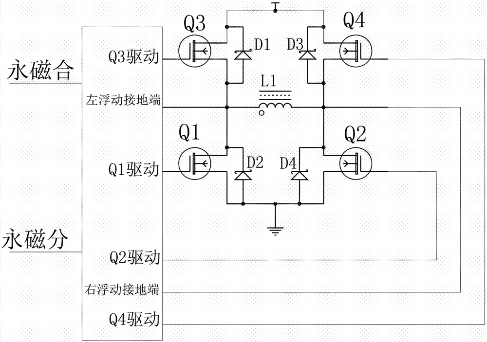
[0070] On the basis of Embodiment 1, the switching tube can be replaced by a MOS tube, and the driving principle of the H bridge is as follows:
[0071] This circuit fully considers the driving reliability of the H bridge, and completely avoids the direct connection of the upper and lower bridge arms during the circuit design. The specific truth table is shown in Table 1:
[0072] Table 1 Driving truth table of H bridge
[0073]
[0074] The working principle of the circuit is as follows: the circuit is mainly composed of two comparators, four optocouplers...
Embodiment 3
[0083] See Figure 1-5 , on the basis of embodiment 1, a kind of working method of permanent magnet coil drive circuit, comprises:
[0084] ① The permanent magnet coupling and permanent magnet sub-control signals output by the processor are respectively connected to the non-inverting terminals of the first comparator 101 and the second comparator 201; wherein the high level of the permanent magnet coupling and permanent magnet sub-control signals is 5V, The low level is 0V; the power supply voltage of the first comparator 101 and the second comparator 201 is 5-20V, generally 13V; the power supply of the comparison level circuit is also 13V;
[0085]② If the permanent magnet coupling control signal is high level, and the permanent magnet sub-control signal is low level, then the voltage at the non-inverting terminal of the first comparator 101 is higher than the voltage at the inverting terminal, and the first comparator 101 outputs a high level to control the first low-side d...
PUM
 Abstract
Description
Claims
Application Information
 - R&D Engineer
- R&D Manager
- IP Professional
- Industry Leading Data Capabilities
- Powerful AI technology
- Patent DNA Extraction
Browse by: Latest US Patents, China's latest patents, Technical Efficacy Thesaurus, Application Domain, Technology Topic, Popular Technical Reports.
© 2024 PatSnap. All rights reserved.Legal|Privacy policy|Modern Slavery Act Transparency Statement|Sitemap|About US| Contact US: help@patsnap.com