Floating photovoltaic device and floating photovoltaic power generation array formed by same

A photovoltaic device and floating technology, applied in the field of photovoltaic module structure, can solve the problems of unutilized water area, poor wind and wave resistance and safety, and complicated installation, and achieve the effects of low structural cost, improved wind and wave resistance, and simple operation.

Inactive Publication Date: 2012-10-17
TRINASOLAR CO LTD
View PDF4 Cites 8 Cited by
  • Summary
  • Abstract
  • Description
  • Claims
  • Application Information

AI Technical Summary

Problems solved by technology

[0002] When photovoltaic modules are actually used outdoors, support devices are needed to ensure safe and reliable operation of the modules. Usually, photovoltaic modules are installed on land, but more than 70% of the water area on the earth has not been utilized.
However, the installation of photovoltaic modules on water areas needs to consider the harm of wind and waves to the photovoltaic system. US patent document US 2009 / 0133732 A1 discloses a floating solar device and method, which can realize the installation of photovoltaic modules on water areas. device, and installed on a solid keel, but the installation is more complicated and the cost will be high; European patent document WO 2011 / 100590 A2 discloses a floating solar power station, the design is similar to a honeycomb structure, and the movable pulley block and the floating device are used to The support frame floats on the water, and the photovoltaic modules are placed in the central area of ​​each hexagonal floating support frame. Large arrays can be assembled and combined by small arrays, but the wind and wave resistance and safety are slightly poor.

Method used


Image

  • Floating photovoltaic device and floating photovoltaic power generation array formed by same
  • Floating photovoltaic device and floating photovoltaic power generation array formed by same
  • Floating photovoltaic device and floating photovoltaic power generation array formed by same

Examples


Embodiment Construction

[0025] Such as Figure 7 , 8 A floating photovoltaic device shown in and 9 includes a module unit 1 and a central control cabin 2. The module unit 1 surrounds the central control cabin 2 and is flexibly connected to the central control cabin 2. The central control cabin 2 confluences the surrounding module units. 1 of the electric energy, and it provides power to the outside centrally.

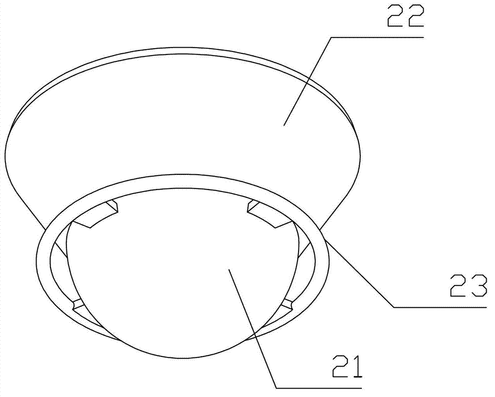
[0026] Such as figure 2 As shown, the central control cabin 2 and the component unit 1 are flexibly connected by means of anchor cables. The central control chamber 2 is divided into a buoyancy chamber 21 at the bottom and an electromechanical chamber 22 at the top. The buoyancy chamber 21 is used to provide buoyancy for the entire central control chamber 2, and the electromechanical chamber 22 is used to concentrate the power of each component unit 1 and provide a power output interface. , and control the buoyancy of the buoyancy chamber 21 and the buoyancy device of the module unit 1.

...


PUM


Abstract

The invention relates to a floating photovoltaic device and a floating photovoltaic power generation array formed the same. The photovoltaic device comprises component units and a central control bin, wherein the component units surround the central control bin and are in flexible connection with the central control bin; the central control bin gathers electric energy of the surrounding component units and supplies power to the outside intensively; adjacent component units are flexibly connected; the component units are provided with floating devices which can control the buoyancy force. A plurality of floating photovoltaic devices provided by the invention can be combined to form a larger floating photovoltaic power generation array; and the adjacent component units of the adjacent floating photovoltaic devices are connected flexibly. The invention has the advantages that the floating photovoltaic device can be arranged in water area safely and reliably and can control the wind and wave resistance of the floating device. A large photovoltaic power station can be formed by assembling the floating photovoltaic devices, the operation in the whole installation process is simple, and the structural cost is low.

Description

technical field [0001] The invention relates to the technical field of photovoltaic module structures, in particular to a floating photovoltaic device and a floating photovoltaic power generation array formed therefrom. Background technique [0002] When photovoltaic modules are actually used outdoors, support devices are needed to ensure safe and reliable operation of the modules. Usually, photovoltaic modules are installed on land, but more than 70% of the water area on the earth has not been utilized. However, the installation of photovoltaic modules on water areas needs to consider the harm of wind and waves to the photovoltaic system. US patent document US 2009 / 0133732 A1 discloses a floating solar device and method, which can realize the installation of photovoltaic modules on water areas. device, and installed on a solid keel, but the installation is more complicated and the cost will be high; European patent document WO 2011 / 100590 A2 discloses a floating solar power...

Claims


Application Information

Patent Timeline
IPC IPC(8): H02N6/00H01L31/042H02S10/40H02S20/30
CPCY02E10/50
Inventor 徐建美
Owner TRINASOLAR CO LTD
Why Eureka
Try Eureka