Transmit-receive sharing dual-polarization waveguide array antenna

A dual-polarized antenna and dual-line polarized technology, applied to antenna arrays, antennas, waveguide horns, etc., can solve the problems of low antenna efficiency, low aperture utilization, and cumbersome procedures, so as to reduce loss and improve aperture utilization efficiency, the effect of high antenna efficiency

Active Publication Date: 2012-10-17
NO 54 INST OF CHINA ELECTRONICS SCI & TECH GRP
View PDF5 Cites 19 Cited by
  • Summary
  • Abstract
  • Description
  • Claims
  • Application Information

AI Technical Summary

Problems solved by technology

[0003] 1. A dual-polarized antenna can be formed by using waveguide slot array antennas in two directions, but the two polarized antennas cannot share the aperture, so the aperture utilization rate is low, and it cannot be used as a phased array antenna
[0004] 2. Use the waveguide wide-side slot antenna and the narrow-side slot antenna to realize the dual-polarized shared aperture, but after the integrated design of the two, the array spacing is at least the sum of the broad side and narrow side of the waveguide. If the array antenna is used, it cannot meet the requirements of the scanning range, so it cannot be used as a phased array antenna
[0005] 3. The shared aperture dual-linear polarized array antenna can be formed by using the microstrip array form, but due to the low efficiency of the microstrip antenna and the large loss of the microstrip feed network, its efficiency is low
[0006] 4. Use the narrow-side waveguide slot antenna and the narrow-side waveguide wall to form the horn antenna to realize the dual-polarized array antenna form. The efficiency of this array antenna is relatively low, the assembly is difficult, and the process is slightly cumbersome. It is used as a phased array antenna. , only the one-dimensional phase scanning function can be realized, and the two-dimensional scanning cannot be realized

Method used


Image

  • Transmit-receive sharing dual-polarization waveguide array antenna
  • Transmit-receive sharing dual-polarization waveguide array antenna
  • Transmit-receive sharing dual-polarization waveguide array antenna

Examples


Embodiment Construction

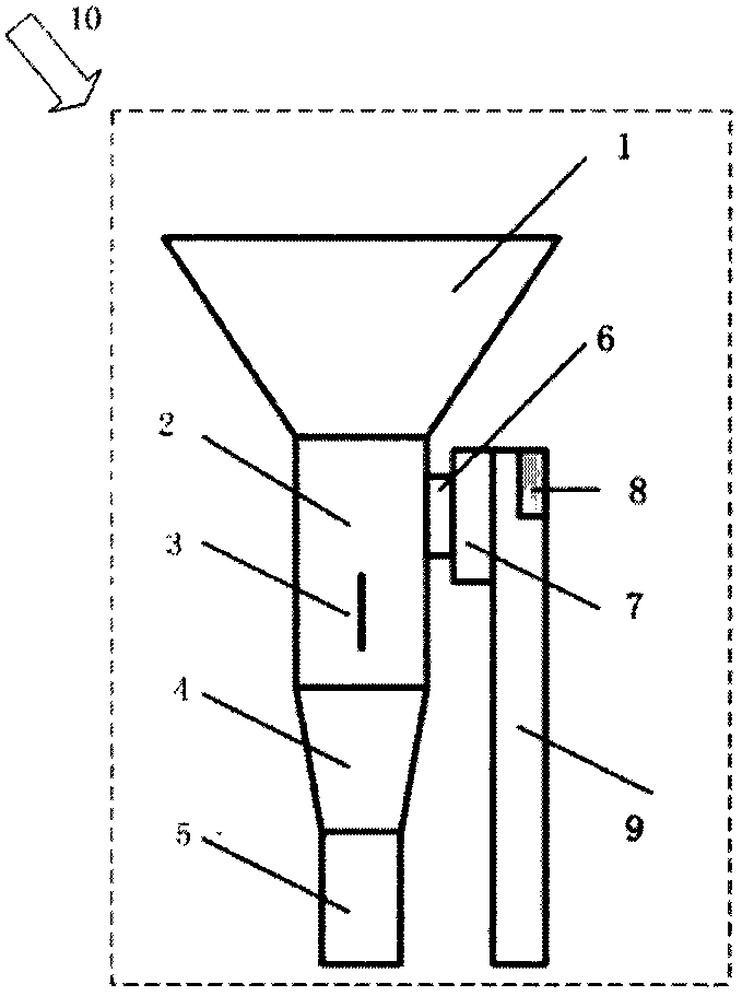
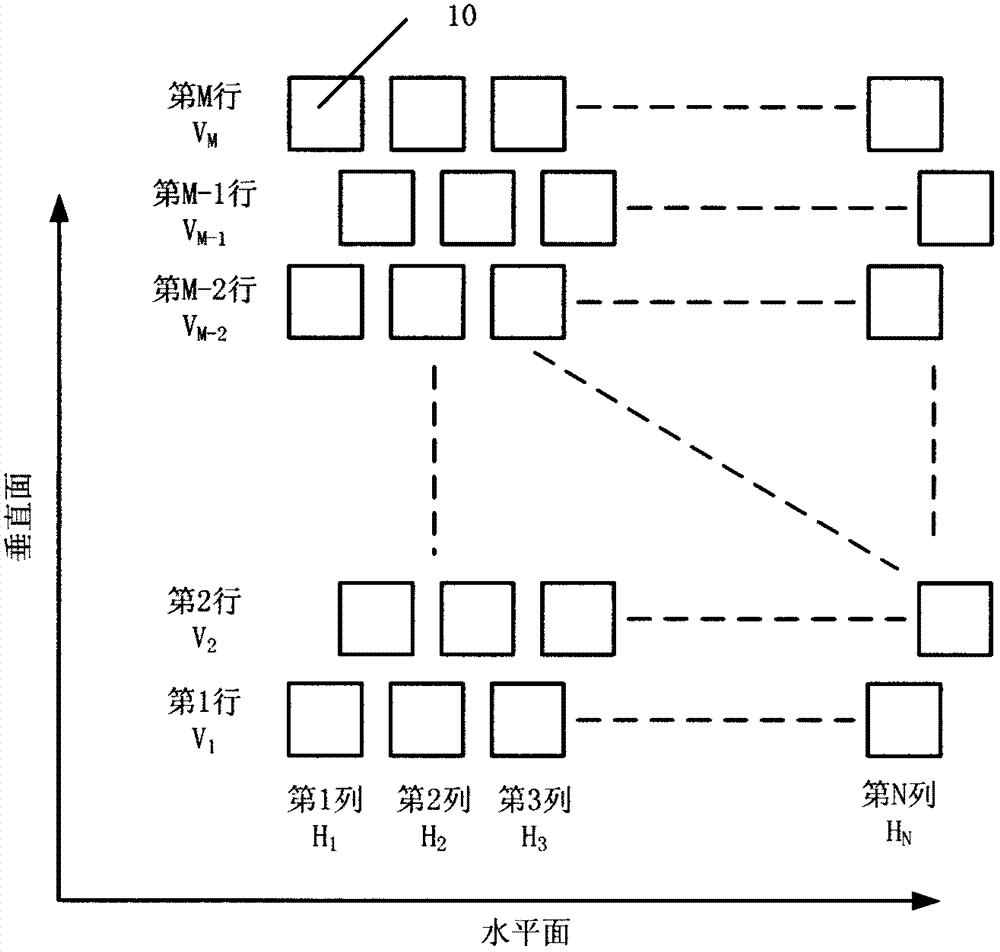
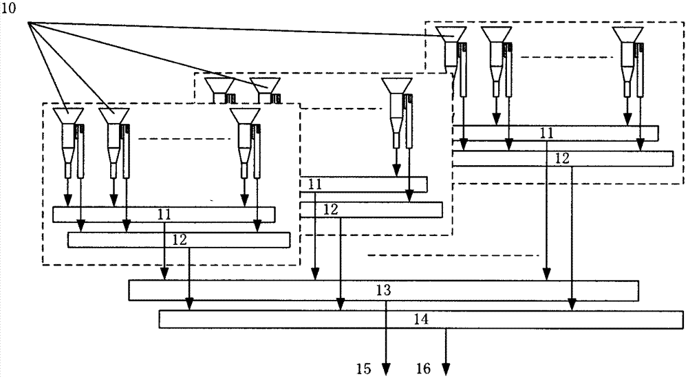
[0025] refer to Figure 1 to Figure 3 , a dual-polarized waveguide array antenna shared by transceivers of the present invention includes a dual-polarized antenna unit and a waveguide feeding network, and the dual-polarized antenna unit 10 is composed of a radiation port 1, a main waveguide 2, a transitional waveguide 4, The vertical polarization waveguide 5, the horizontal polarization waveguide 9 and the polarization conversion waveguide 7 are composed; the upper end of the main waveguide 2 is connected with the radiation port 1, the lower end of the main waveguide 2 is connected with the upper end of the transition waveguide 4, and the lower end of the transition waveguide 4 is connected with the vertical The polarization waveguide 5 is connected; the horizontal polarization waveguide 9 is connected to the side port of the polarization conversion waveguide 7 , and the polarization conversion waveguide 7 is connected to the main waveguide 2 through the coupling slot 6 arrange...


PUM


Abstract

The invention discloses a transmit-receive sharing dual-polarization waveguide array antenna, which comprises a dual-polarization antenna unit and a waveguide feed network, wherein the dual-polarization antenna unit is composed of a radiation port, a main waveguide, a transition waveguide, a vertical polarization waveguide, a horizontal polarization waveguide and a polarization switching waveguide. A method of a horizontal polarization and a vertical polarization sharing the same one aperture is utilized, so that the aperture utilization efficiency of the antenna is increased. The horizontal polarization and the vertical polarization adopt a waveguide feed mode, so that the loss of the feed network is reduced, and the antenna has high antenna efficiency. Two polarizations to a radiation unit adopt the same polarization feed mode, wherein the vertical polarization is direct feed, the radiation to the horizontal polarization adopts the vertical polarization feed, and the horizontal polarization of the radiation is realized through a waveguide step transition and slot-coupling mode.

Description

technical field [0001] The technical field involved in the design of the present invention is not only in the communication field, but also has a considerable application background in electronic countermeasures, radar, remote sensing and the like. The invention is especially suitable for manufacturing low-profile satellite mobile communication, radar and dual-linear polarization array antennas in other systems, and is also especially suitable for dual-linear polarization one-dimensional or two-dimensional phased array antennas or linear polarization angle adjustable polarized array antenna. Background technique [0002] At present, the dual-linear polarized antennas or phased array antennas used in the communication system have the following forms. Although they have their own characteristics in performance, they all have certain deficiencies. [0003] 1. A dual-polarized antenna can be formed by using waveguide slot array antennas in two directions, but the two polarized ...

Claims


Application Information

Patent Timeline
Patent Type & Authority Applications(China)
IPC IPC(8): H01Q13/02H01Q15/24H01Q21/00
Inventor 韩国栋武伟杜彪
Owner NO 54 INST OF CHINA ELECTRONICS SCI & TECH GRP
Why Eureka
Try Eureka