
Rocker switch

A rocker switch and electrical connection technology, which is applied to the components of the flip switch/rocker switch, etc., can solve the problems of short service life and large wear and tear of the switch contact bridge, so as to reduce wear, prolong service life and reduce friction force effect

Inactive Publication Date: 2012-10-03
HUANGSHAN AOTESI ELECTRICAL CO LTD
View PDF4 Cites 3 Cited by
  • Summary
  • Abstract
  • Description
  • Claims
  • Application Information

AI Technical Summary

Problems solved by technology

[0003] The purpose of the present invention is to provide a rocker switch to solve the problems of high wear and short life of the switch contact bridge

Method used


Image

  • Rocker switch
  • Rocker switch
  • Rocker switch

Examples


Embodiment Construction

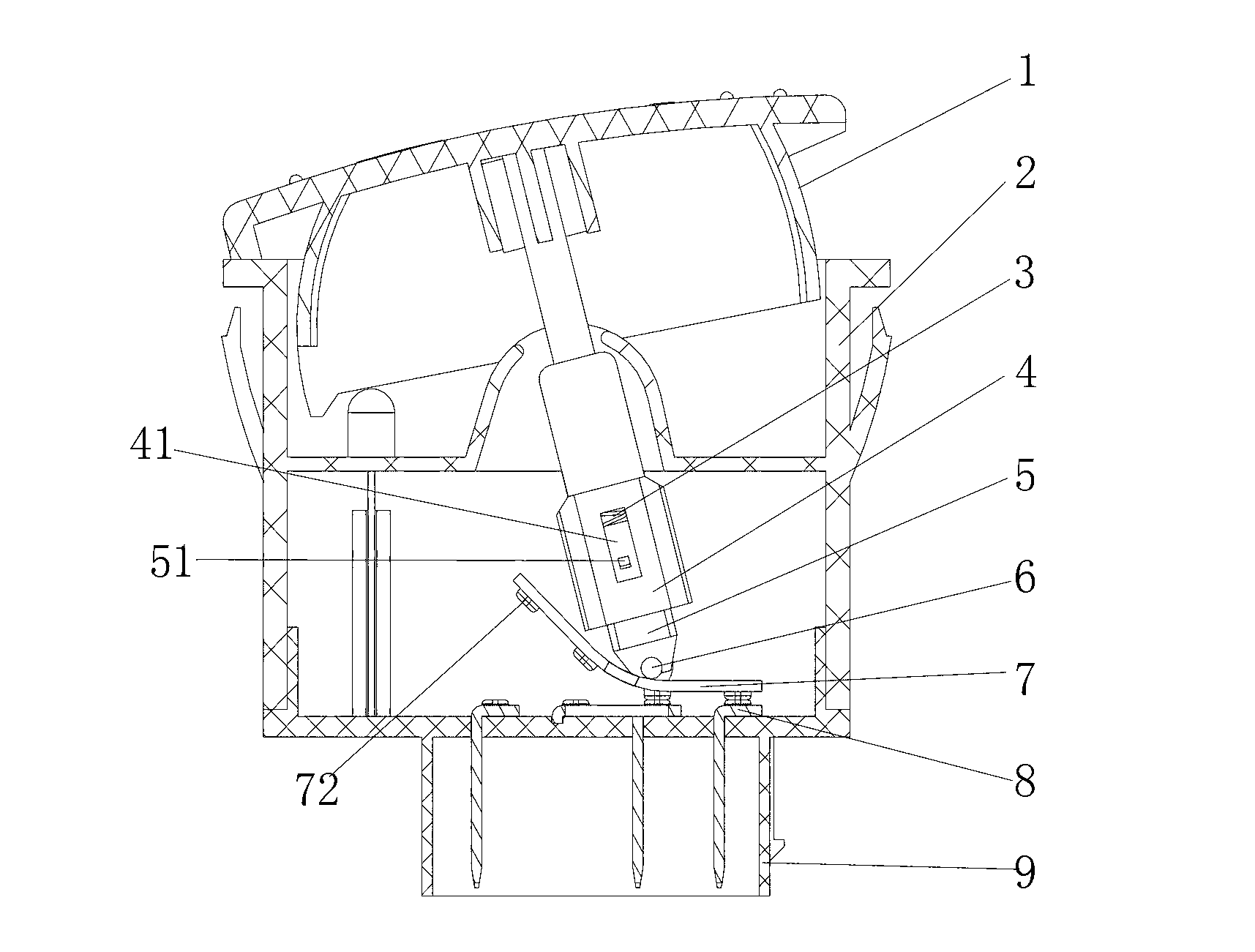
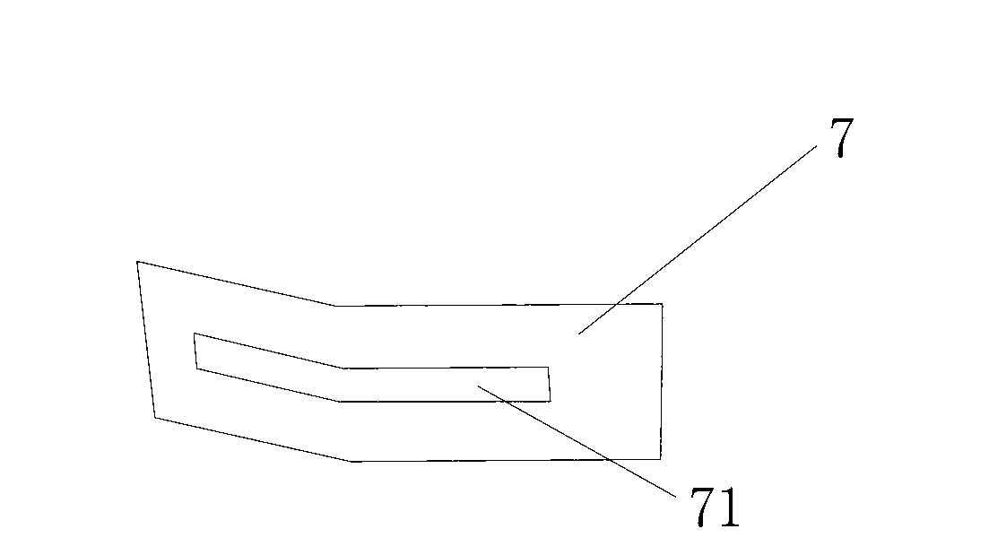
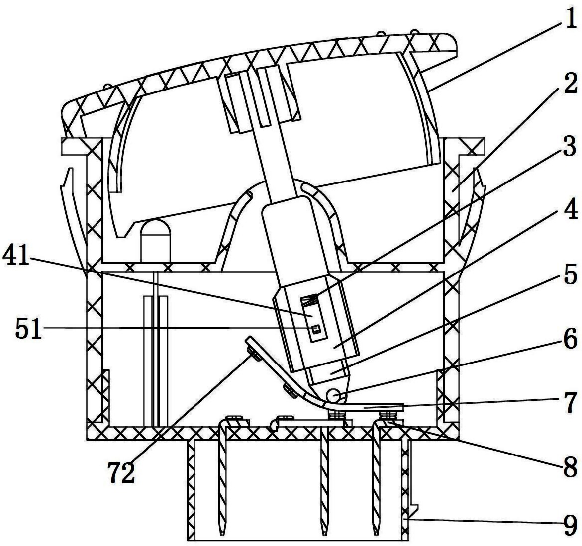
[0012] Such as figure 1 , figure 2 As shown, a rocker switch includes a button 1 , a base 9 , an electrical connection insert 8 fixed on the base 9 , a contact bridge 7 matched with the electrical connection insert 8 , and a housing 2 that fixes the base 9 . The button 1 is located at the end of the shell 2 away from the base 9 . A rotating block 4 is fixedly connected to the button 1, the lower half of the rotating block 4 is a column structure, the upper half of the transmission block 5 is sleeved in the lower half of the rotating block 4, and the upper end surface of the transmission block 5 is connected to the rotating block. A spring 3 that plays a return role is also provided between the inner walls of the block 4; the transmission block 5 can move in the axial direction, and a rectangular hole 41 along the spring expansion and contraction direction is opened on the side wall of the rotating block 4; The outer wall of 5 is provided with a boss 51 structure, and boss 5...


PUM


Abstract

A rocker switch with a scroll wheel structure comprises a button, a base, an electric connection insert which is fixed on the base, a contact bridge which is matched with the electric connection insert and a shell for fixing the base, and is characterized in that a turning block is fixedly connected to the button, the lower half part of the turning block is of a tubular column structure, an upper half part of a transmission block is sleeved in the lower half part of the turning block, and a spring which has a return effect is also arranged between the transmission block and the turning block; the lower end of the transmission block is movably connected with a pulley, and the pulley is pressed on the contact bridge; and the contact bridge is in a bending strip structure, and the bending is positioned at the middle position of the contact bridge. The abrasion of the contact bridge can be reduced, the service life of the contact bridge is prolonged, the operation handfeel of the button is improved, and the rocker switch with the scroll wheel structure has a simple structure, is convenient to assemble, and can be widely applied in the automotive switch field.

Description

technical field [0001] The invention relates to an automobile switch, in particular to a rocker switch with a roller structure. Background technique [0002] Usually, products like rocker switches generally use brass support pins to drive the connection and disconnection between the contact bridge and the insert to realize the work of the product. However, the friction and damage between the support pin and the contact bridge made of brass are large under working conditions, resulting in poor hand feeling and a serious reduction in life. The solution of the prior art: 1. Increase the elasticity of the spring; 2. The surface treatment of the support pin and the contact bridge parts is smooth. In the actual application of the above-mentioned existing technical solutions, the precision machining of parts is required to be high, and the cost is increased, but the actual effect may not be ideal. Contents of the invention [0003] The object of the present invention is to prov...

Claims


Application Information

Patent Timeline
Patent Type & Authority Applications(China)
IPC IPC(8): H01H23/12H01H23/16
Inventor 胡松林宋玉斌
Owner HUANGSHAN AOTESI ELECTRICAL CO LTD
Learn More