Method and device for automatically removing electromagnetic coupling in induced polarization measurement

A technology of excitation polarization and electromagnetic coupling, applied in the field of electromagnetic coupling, which can solve the problems of cumbersome work, difference in excitation polarization potential, and poor effect.

Active Publication Date: 2012-10-03
湖南继善高科技有限公司
View PDF4 Cites 5 Cited by
  • Summary
  • Abstract
  • Description
  • Claims
  • Application Information

AI Technical Summary

Problems solved by technology

However, since the excited polarization itself is also a process of gradually decaying and disappearing with time, when the electromagnetic coupling disappears, most of the excited polarization itself is also attenuated, and only a small residual excited polarization potential difference can be measured
Therefore, the method of delaying the measurement time to overcome the electromagnetic coupling is not effective.
In addition, corrections for electromagnetic coupling potential differences have also been used in the past to reduce electromagnetic coupling in induced polarization measurements, but the correction requires prior knowledge of local electromagnetic coupling and requires additional field or indoor calculation work The amount, the work is cumbersome, and the effect is not good
So far there is no method and device for automatically removing electromagnetic coupling in excited polarization measurement

Method used


Image

  • Method and device for automatically removing electromagnetic coupling in induced polarization measurement
  • Method and device for automatically removing electromagnetic coupling in induced polarization measurement
  • Method and device for automatically removing electromagnetic coupling in induced polarization measurement

Examples


Embodiment Construction

[0054] The present invention will be further described below in conjunction with drawings and embodiments.

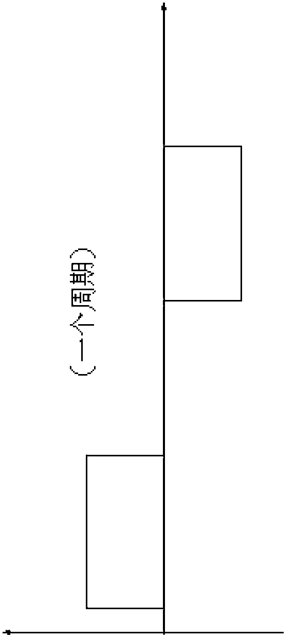
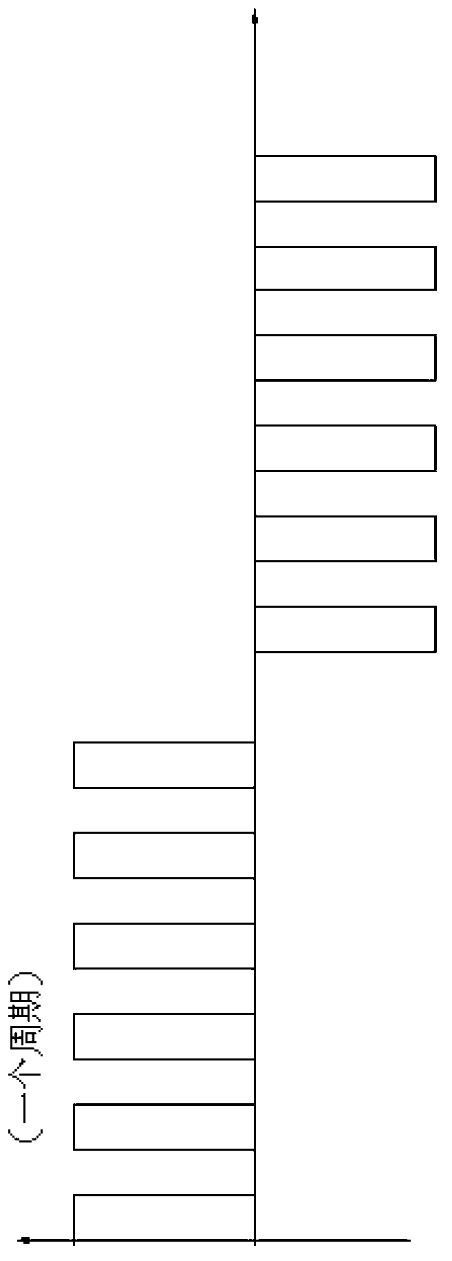
[0055] The induced polarization method needs to send an excitation current to the ground through two power supply electrodes. The commonly used excitation current waveform is a bipolar rectangular wave of equal width (see Figure 1 ( a )) and the dual-frequency synthesized current waveform (Fig. 1 ( b ))Wait. In order to eliminate the serious influence of electromagnetic coupling in induced polarization measurement, many methods proposed by predecessors cannot achieve ideal results. The previous methods either increase the workload in the field, or increase the indoor calculation.

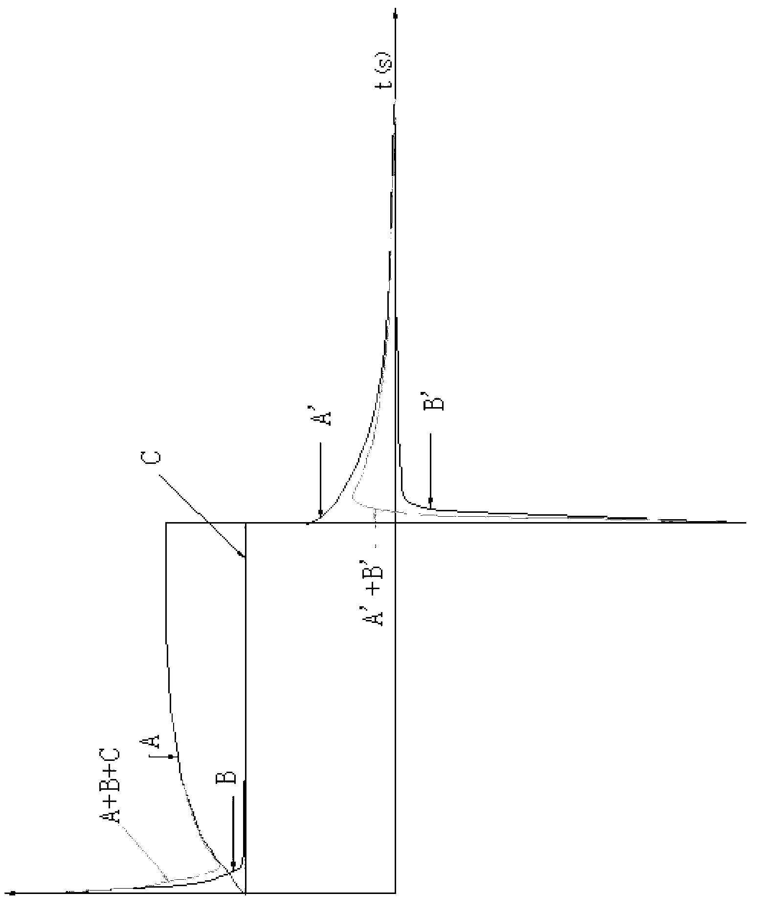
[0056] Taking rectangular pulse excitation as an example, the principle on which the present invention is based is further described.

[0057] figure 2 Among them, A represents the excited polarization potential difference when the current pulse is turned on, B represents the electromagne...


PUM


Abstract

The invention discloses a method and device for automatically removing electromagnetic coupling in induced polarization measurement. The method comprises the following steps of: (1) transmitting special waveform pulse current to the underground, wherein the special waveform pulse current is taken as an exciting current source of an induced polarization method; and (2) receiving earth current response of the special waveform pulse current, wherein the earth current response is earth current response containing an induced polarization potential difference, an electromagnetic coupling potential difference and a direct current potential difference; integrating the earth current response, automatically removing the electromagnetic coupling potential difference in the induced polarization measurement, and extracting a pure induced polarization potential difference or direct current potential difference respectively. The invention further discloses a device for automatically removing electromagnetic coupling in induced polarization measurement. Due to the adoption of the method and the device, the electromagnetic coupling influence can be removed automatically in an induced polarization measuring process, underground information reflecting deep ore resources is extracted, the increase in the exploration depth of an induced polarization method is facilitated, the exploration result of the induced polarization method is enhanced, and more ore resources are provided for economic development.

Description

technical field [0001] The invention relates to a method and a device for automatically removing electromagnetic coupling in excitation polarization measurement in the field of geophysical exploration. Background technique [0002] Electromagnetic coupling is a phenomenon of electromagnetic induction caused by changes in electric (magnetic) fields over time. The more intense the electric (magnetic) field changes with time, the stronger the electromagnetic coupling, and the more serious its influence on the excited polarization measurement. [0003] With the rapid development of the economy, the shallow mineral resources have been developed in large quantities, and it is urgent to increase the exploration depth of the induced polarization method, requiring a larger polar distance. The electromagnetic coupling interference in the induced polarization measurement is more prominent when the pole distance is increased (because the influence degree of electromagnetic coupling is ...

Claims


Application Information

Patent Timeline
Patent Type & Authority Applications(China)
IPC IPC(8): G01V3/06
Inventor 何继善
Owner 湖南继善高科技有限公司
Why Eureka
Try Eureka